At Arduino Expert, we designed and developed a custom Arduino Leonardo gaming steering wheel and speed control system for a client who required a physical controller for a computer-based driving game.
The project combines Arduino programming, electronic circuit development, USB game-controller integration, mechanical product design and 3D printing. A KY-040 rotary encoder was mechanically connected to the steering wheel to detect left and right rotation, while a limit switch was used as the input mechanism for the gas pedal.
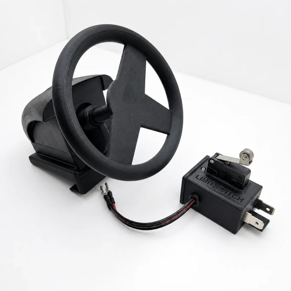
To turn the electronic prototype into a complete and usable product, we also designed and 3D printed the steering wheel, the main electronics enclosure and a separate enclosure for the pedal limit switch.
This client project demonstrates how our Product Design and Development Services bring electronics, embedded programming, mechanical design and rapid prototyping together in one complete solution.
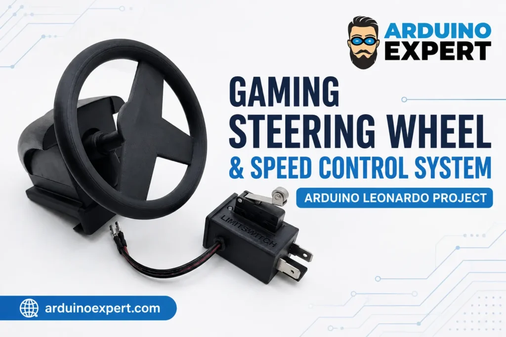
Driving Wheel Project Overview
The purpose of this project was to develop a compact physical controller that could provide steering and speed-control inputs for a computer driving game.
Instead of controlling the game with a keyboard, the user could rotate a physical steering wheel and press a gas pedal. The movement of the steering wheel was detected by a rotary encoder and processed by the Arduino Leonardo. The steering position was then converted into a USB game-controller X-axis value.
The final prototype included:
- Arduino Leonardo-based controller electronics
- KY-040 rotary encoder steering input
- Limit-switch gas pedal input
- USB game-controller firmware
- Custom-designed steering wheel
- 3D-printed electronics enclosure
- Custom gas-pedal switch enclosure
- Circuit wiring and hardware integration
- Firmware testing and controller calibration
The result was a functional, custom-built gaming controller developed according to the client’s specific requirements.
Client Requirements
The client needed a simple but functional gaming steering system that would provide a more interactive driving experience than standard keyboard controls.
The main requirements were:
- A physical steering wheel for left and right vehicle control
- A reliable sensor for detecting steering-wheel rotation
- A gas pedal for controlling vehicle speed
- USB communication with a computer
- Compact housing for the Arduino and electronic components
- A custom-designed steering wheel rather than a standard commercial wheel
- A protected enclosure for the pedal limit switch
- Firmware that could translate physical movement into game-control values
- A design that could be assembled, tested and demonstrated as a working prototype
The project therefore required more than Arduino programming alone. It involved electronic integration, embedded firmware, mechanical design, product prototyping and 3D printing.
Our Custom Arduino-Based Solution
We selected the Arduino Leonardo as the main controller because it is suitable for USB human-interface-device applications.
The Arduino Leonardo reads the KY-040 rotary encoder, calculates the steering direction and position, and sends the resulting value to the connected computer as a game-controller input.
A limit switch installed inside the gas-pedal enclosure provides the speed-control command. When the user presses the pedal, the switch changes state. The Arduino firmware detects this input and gradually increases the software speed value. When the pedal is released, the firmware gradually reduces the value.
The complete solution consisted of four closely integrated parts:
- Steering-wheel rotation detection
- Gas-pedal input and speed-value generation
- Arduino Leonardo USB controller firmware
- Custom 3D-designed and 3D-printed mechanical components
Related Arduino Project: Interested in another Arduino project that measures rotational movement? Explore our Arduino Measurement Wheel Device for Wood-Cutting Saw to learn how a rotary encoder can track wheel movement and calculate precise distances.
How the Gaming Steering Wheel Works?
1. Steering Input Using the KY-040 Rotary Encoder
The KY-040 is an incremental rotary encoder that provides two digital output signals, normally identified as CLK and DT.
These two signals allow the Arduino to determine:
- Whether the steering wheel is rotating
- Whether it is moving clockwise
- Whether it is moving counterclockwise
- How many encoder steps have occurred
In this project, the rotary encoder was mechanically connected to the custom steering wheel. When the user turned the wheel, the encoder generated a sequence of digital pulses.
The Arduino Leonardo monitored these pulses and increased or decreased an internal steering-position variable according to the direction of rotation.
The steering value was restricted to a defined minimum and maximum range to prevent it from moving outside the expected controller limits.
2. Converting Encoder Movement into Game Steering
The raw encoder position was converted into a suitable game-controller value. The mapped value represented the following steering states:
- A negative value represented steering in one direction
- A value near zero represented the centre position
- A positive value represented steering in the opposite direction
The Arduino then updated the game-controller X-axis using the Joystick library.
This allowed the computer or client application to interpret the physical steering-wheel movement as a standard controller-axis input.
3. Steering Sensitivity Adjustment
A 10kΩ potentiometer is used to adjust the steering wheel sensitivity. Rotating it allows the user to choose between smoother steering control and faster, more responsive movement.
Interrupt-Based Rotary Encoder Reading
The encoder clock signal was connected to an interrupt-capable Arduino Leonardo pin.
An interrupt was used so that steering changes could be detected as soon as an encoder pulse occurred. This is more responsive than checking the encoder only occasionally inside the main program loop.
Whenever the required edge was detected on the encoder clock signal, the interrupt function read the DT signal and determined the rotation direction.
The firmware then:
- Detected an encoder pulse
- Read the second encoder channel
- Determined clockwise or counterclockwise movement
- Increased or decreased the steering position
- Restricted the position to the permitted range
- Mapped the position to a game-controller axis
- Sent the updated steering value to the computer
This approach created a direct relationship between physical wheel rotation and the digital steering command.
Gas Pedal and Speed Control Using a Limit Switch
A limit switch was used inside the gas-pedal mechanism.
One side of the switch was connected to Arduino Leonardo digital pin 4, while the other side was connected to GND. The Arduino input was configured with the internal pull-up resistor.
Under this arrangement:
- The input remains HIGH while the pedal is not pressed
- The input becomes LOW when the pedal presses the limit switch
Because a limit switch is a digital device, it normally provides only two states: pressed and released. However, the project firmware used software logic to create a gradually changing speed value.
Progressive Acceleration Logic
When the pedal was pressed, the firmware increased the speed variable. The value was restricted to a defined maximum so that it could not continue increasing indefinitely.
This created a software-based acceleration effect instead of changing instantly from zero to maximum speed.
Progressive Deceleration Logic
When the pedal was released, the firmware gradually decreased the speed value.
The value was prevented from falling below zero. This produced a smoother deceleration response for the client’s gaming application.
This solution allowed a simple mechanical limit switch to provide more useful speed-control behaviour without requiring an analog pedal sensor.
It is important to note that the physical switch itself remains a digital ON/OFF input. The gradual acceleration and deceleration are generated by the Arduino firmware.
Arduino Leonardo USB Game Controller
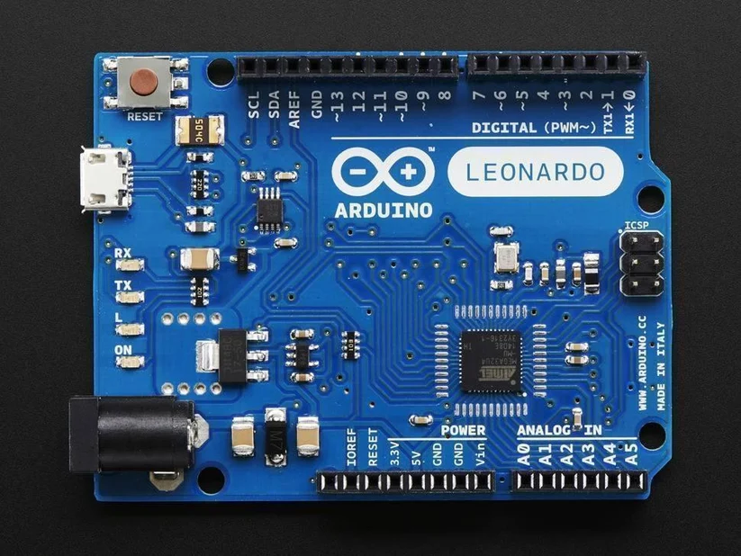
The Arduino Leonardo was configured as a USB gamepad using the Arduino Joystick library.
When connected to a computer through USB, the controller could provide the steering-axis information required by the gaming application.
The firmware created a gamepad configuration with the X-axis enabled for steering. Unnecessary controller inputs were disabled to keep the HID report focused on the functions required by the project.
The main USB controller operations included:
- Initializing the Joystick library
- Defining the controller as a gamepad
- Setting the X-axis input range
- Mapping encoder movement to the X-axis
- Continuously updating the steering input
- Generating and monitoring the speed-control value
- Providing Serial output for testing and client software integration
Depending on the final game or computer application, controller calibration or input assignment may be required before use.
Circuit Diagram of Driving Wheel Project with Arduino Leonardo
The electronic circuit was intentionally kept compact and straightforward. The circuit Diagram is given below.
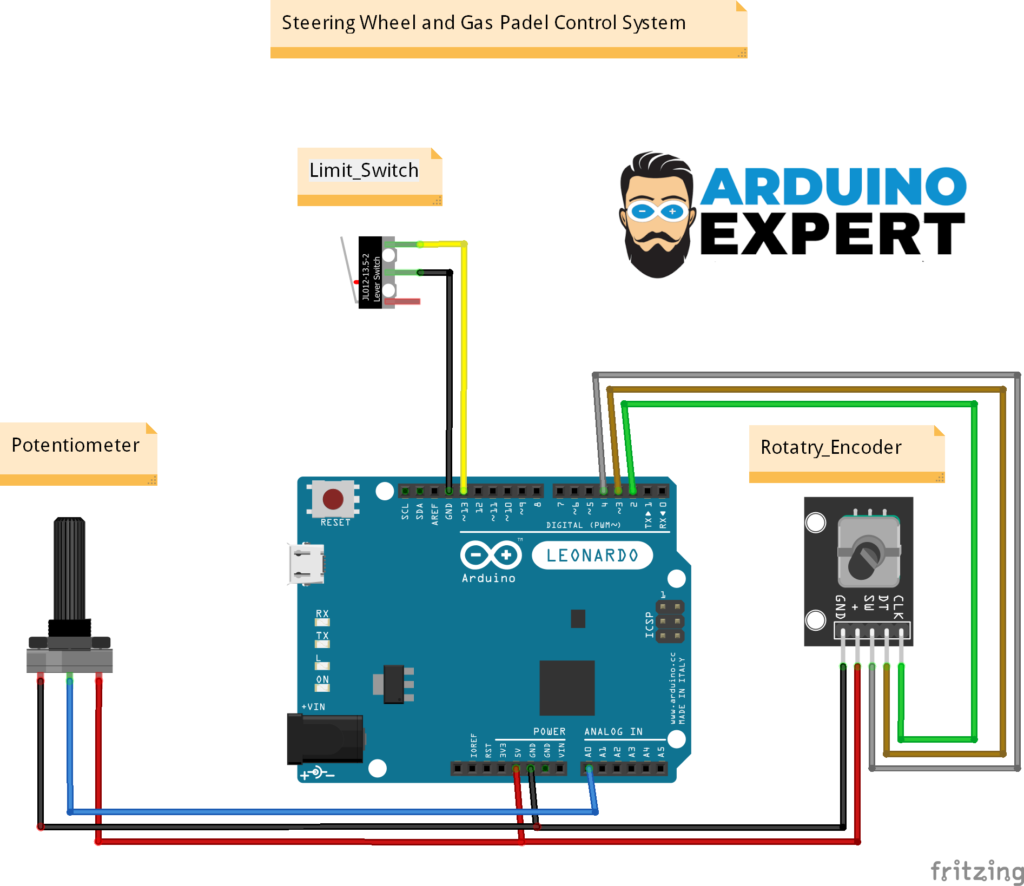
Connections Description:
| Arduino Leonardo connection | Connected component | Purpose |
|---|---|---|
| 5V | KY-040 positive pin | Supplies power to the rotary encoder |
| GND | KY-040 GND | Common electrical ground |
| Digital pin 2 | KY-040 CLK | Encoder clock and interrupt signal |
| Digital pin 3 | KY-040 DT | Encoder direction signal |
| Digital pin 13 | Limit switch | Gas-pedal input |
| Analog Pin A0 | Potentiometer | Steering Wheel Sensitivity Adjustment |
| GND | Second limit-switch terminal | Completes the switch circuit |
| USB port | Computer | Power and data communication |
Components Used in Gaming Steering Wheel and Speed Control System
1. Arduino Leonardo
The Arduino Leonardo acts as the main controller. It reads the steering and pedal inputs, processes the firmware logic and communicates with the computer through USB.
2. KY-040 Rotary Encoder
The rotary encoder detects wheel rotation and direction. It converts the mechanical movement of the steering wheel into digital pulses that can be processed by the Arduino.
3. Potentiometer
Used to adjust the steering wheel sensitivity according to the user’s preference.
4. Limit Switch
The limit switch detects whether the gas pedal is pressed or released. Firmware logic converts this digital input into a progressively changing speed value.
5. Custom Steering Wheel
The steering wheel was designed specifically for this client project. Its dimensions and internal mounting arrangement were developed to work with the selected encoder and enclosure.
6. 3D-Printed Electronics Enclosure
A custom enclosure was designed to hold and protect the Arduino Leonardo, rotary encoder and associated wiring.
7. 3D-Printed Gas-Pedal Enclosure
A separate mechanical enclosure was developed for the limit switch. It positioned the switch correctly so that it could be activated through the pedal mechanism.
8. USB Cable and Wires
A USB connection provides power and communication between the Arduino Leonardo and the computer. Internal wiring connects the encoder and pedal switch to the controller.
Arduino Firmware Development
The firmware was developed to coordinate the rotary encoder, limit switch, USB gamepad and speed-control logic.
The main stages of the program include:
Pin Definition
The firmware defines separate digital pins for:
- Encoder clock
- Encoder direction
- Gas-pedal switch
Using named pin definitions makes the code easier to understand, troubleshoot and modify.
Input Configuration
The encoder channels are configured as digital inputs.
The limit switch is configured as INPUT_PULLUP, allowing the Arduino Leonardo’s internal pull-up resistor to maintain a stable default state without requiring an additional external resistor.
Joystick Initialization
The program initializes the Arduino Joystick library and creates a gamepad configuration.
The steering input is represented through the X-axis. The firmware also defines the permitted X-axis value range before controller operation begins.
Encoder Interrupt
An interrupt is attached to the encoder clock pin. When a falling edge occurs, the encoder-reading function checks the DT signal and determines the rotation direction.
Steering-Position Limiting
The internal encoder position is prevented from moving beyond its programmed minimum and maximum values.
This protects the mapped controller output from exceeding the expected range.
Steering-Value Mapping
The encoder position is converted to the selected negative-to-positive joystick-axis range.
The mapped value is sent to the computer as the X-axis game-controller input.
Sensitivity Potentiometer Reading
The firmware reads the 10kΩ sensitivity potentiometer through analog pin A0. Its analog value is mapped to a predefined sensitivity range and applied to the steering calculation before the final value is sent to the USB controller X-axis.
Pedal and Speed Logic
The program continuously checks the limit-switch state.
When the pedal is pressed, the speed value increases. When it is released, the speed value decreases. Minimum and maximum limits are applied to keep the result within the required range.
Serial Monitoring
Serial output is used to display the calculated speed value.
This is useful for:
- Firmware debugging
- Speed-value verification
- Client software integration
- Testing acceleration and deceleration
- Adjusting the speed increment
- Confirming pedal-switch operation
Custom Steering Wheel Product Design
A major part of the project was the mechanical design of the steering wheel and its enclosure.
The steering wheel had to be more than a visual model. It needed to transfer the user’s rotation to the KY-040 encoder while remaining easy to hold and operate.
Important design considerations included:
- Overall wheel dimensions
- Hand grip and usability
- Encoder shaft alignment
- Mechanical coupling between the wheel and encoder
- Support for repeated rotation
- Internal space for electronic components
- Access to the Arduino USB connection
- Wire-routing space
- Component mounting points
- Assembly and disassembly
- Printability of each part
- Protection of the electronics
The final design was prepared for additive manufacturing and divided into practical parts where required for printing and assembly.
Our 3D Design and Modeling Services include custom electronics enclosures, Arduino casings, mechanical supports, sensor mounts and product housings for functional prototypes.
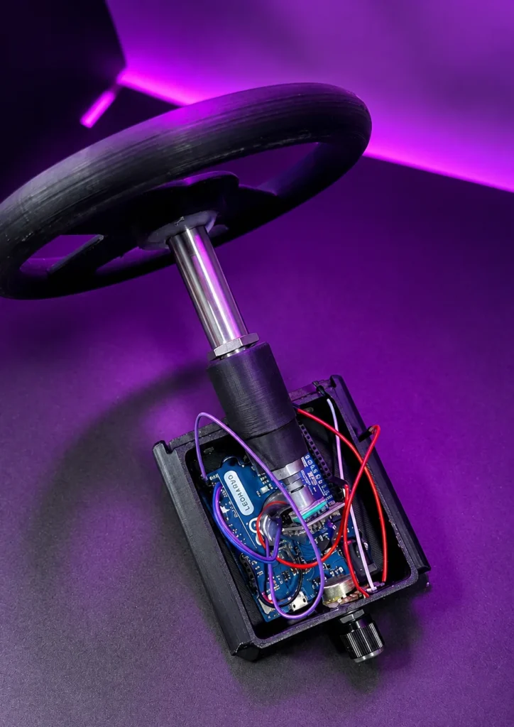
3D-Printed Electronics Enclosure
The main enclosure was designed to organise and protect the controller components.
Instead of leaving the Arduino Leonardo and wiring exposed, the enclosure provided a dedicated structure for the electronics.
The enclosure design considered:
- Arduino Leonardo board dimensions
- Rotary encoder placement
- USB-port accessibility
- Internal cable clearance
- Component mounting
- Mechanical stability
- Opening and closing of the enclosure
- Steering-wheel alignment
- Ease of assembly
- Overall product appearance
A properly designed enclosure improves both the usability and presentation of an electronics prototype.
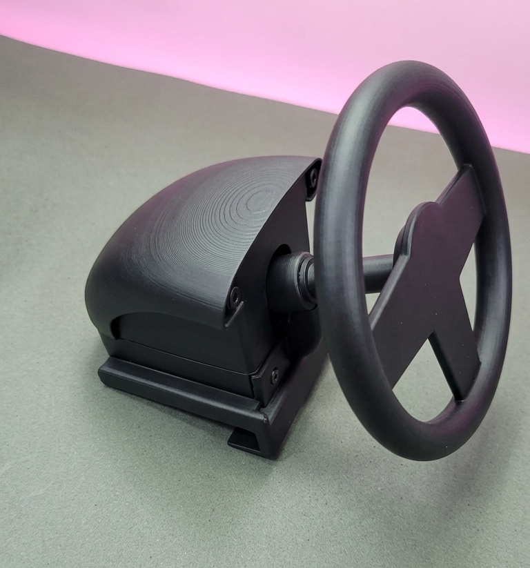
Gas-Pedal Limit-Switch Enclosure
The limit switch also required a custom mechanical housing.
Without a suitable enclosure, the switch could move out of position, receive force at the wrong angle or remain exposed to accidental damage.
The custom pedal enclosure was designed to:
- Secure the limit switch
- Position the switch beneath the pedal mechanism
- Provide consistent switch activation
- Protect the electrical terminals
- Guide the pedal movement
- Allow wiring to pass safely
- Make the assembly easier to test and maintain
This enclosure converted a basic electronic switch into a practical physical control.
The parts were produced through our professional 3D Printing Services, which support functional enclosures, product prototypes, custom mechanical components and electronics housings.
Key Features of Driving Wheel
- Arduino Leonardo-based USB controller
- Physical gaming steering wheel
- KY-040 rotary encoder steering detection
- Clockwise and counterclockwise direction sensing
- Interrupt-based encoder processing
- Steering-position limiting
- USB gamepad X-axis output
- Limit-switch gas pedal
- Firmware-generated progressive acceleration
- Gradual deceleration after pedal release
- Serial speed-value output
- Custom steering-wheel design
- Custom electronics enclosure
- Separate pedal-switch enclosure
- 3D-printed functional parts
- Compact and modular prototype
- Developed for a real client requirement
Challenges and Design Considerations
Translating Unlimited Encoder Rotation into a Limited Steering Range
An incremental rotary encoder can continue generating pulses as it rotates. A game-controller steering axis, however, requires a defined minimum and maximum.
The firmware solved this by maintaining a position variable and restricting it to a specified range before mapping it to the USB X-axis.
Detecting Steering Direction Reliably
The program reads both encoder channels to determine whether the wheel is turning clockwise or counterclockwise.
An interrupt on the clock signal allows steering changes to be processed promptly.
Creating Gradual Speed Control from a Digital Switch
A limit switch only indicates pressed or released. It does not directly measure pedal travel.
The firmware creates a more gradual response by increasing the speed value while the switch is active and decreasing it after release.
Mechanical Connection Between Wheel and Encoder
The steering wheel had to rotate the encoder correctly without poor alignment or unnecessary movement.
This requirement was addressed during the mechanical design of the wheel, shaft interface and enclosure.
Protecting the Pedal Switch
The pedal switch required stable positioning and protection from incorrect mechanical force.
A dedicated 3D-printed enclosure was created to secure the switch and guide its interaction with the pedal.
Possible Future Upgrades
The current system can be expanded according to future client requirements.
Possible upgrades include:
- Analog accelerator pedal using a potentiometer or Hall-effect sensor
- Dedicated USB accelerator-axis output
- Brake pedal
- Clutch pedal
- Paddle shifters
- Gear-selection buttons
- Handbrake input
- Additional steering-wheel buttons
- Centre-position calibration
- Automatic steering-centre detection
- Higher-resolution rotary encoder
- Optical or magnetic steering sensor
- Vibration motor
- Force-feedback system
- Status LEDs
- OLED or LCD display
- Custom desktop calibration software
- Wireless communication
- Improved mechanical bearings
- Adjustable pedal resistance
- Interchangeable steering-wheel designs
These additions would require corresponding updates to the electronics, firmware and mechanical design.
Applications of Steering Wheel Project
This project concept can be adapted for:
- PC driving games
- Basic racing simulators
- Educational gaming projects
- Arduino HID demonstrations
- STEM learning systems
- Interactive exhibition displays
- Driving-training prototypes
- Vehicle-control demonstrations
- Custom arcade machines
- Rehabilitation or coordination exercises
- University embedded-system projects
- Human-machine-interface research
- Product proof-of-concept development
Why Choose Arduino Expert for a Custom Gaming Controller?
At Arduino Expert, we work on complete custom electronics projects rather than limiting our services to code or circuit diagrams.
Depending on the project, our development support can include:
- Requirement analysis
- Microcontroller selection
- Circuit design
- Arduino programming
- Embedded firmware
- Sensor and switch integration
- USB HID controller development
- PCB design
- Product 3D modeling
- Electronics enclosure design
- 3D printing
- Prototype assembly
- Testing and debugging
- Technical documentation
- Future feature development
This integrated approach helps ensure that the firmware, electronics and mechanical design work together as one complete product.
You can also explore our other Arduino projects and our Arduino Racing Cars Game to see additional examples of custom interactive systems.
Conclusion
The Arduino Leonardo Gaming Steering Wheel and Speed Control System is a practical example of combining embedded programming, USB game-controller communication, rotary encoder sensing, mechanical product design and 3D printing.
The KY-040 rotary encoder detects steering-wheel direction and movement, while the Arduino Leonardo converts this information into a game-controller X-axis input. The gas-pedal limit switch provides a simple and reliable user input, with firmware generating progressive acceleration and deceleration behaviour for the client’s application.
Custom 3D-designed and 3D-printed parts transformed the circuit into a complete physical prototype. The steering wheel, electronics enclosure and pedal-switch housing were all developed according to the functional requirements of the system.
This client project reflects our capabilities in Product Design and Development Services, Arduino Project Development Services, custom electronics development, enclosure design and 3D Printing Services.
Need a Custom Arduino Gaming Controller?
Are you planning a custom gaming controller, simulator, interactive product or Arduino-based electronic prototype?
Arduino Expert can help with the complete development process, including circuit design, Arduino programming, USB game-controller integration, mechanical design, enclosure development, 3D printing, assembly and testing.
Frequently Asked Questions
What is the Arduino Gaming Steering Wheel project?
This project shows how to build a DIY gaming steering wheel using an Arduino Leonardo. The steering wheel connects to a computer through USB and works as a game controller for compatible racing games and simulators.
Why is Arduino Leonardo used for this project?
The Arduino Leonardo has built-in USB communication capabilities. It can be programmed to behave like a keyboard, mouse, joystick, or game controller without requiring an additional USB interface.
Does the steering wheel work as a USB game controller?
Yes. After uploading the required program, the Arduino Leonardo can be detected by the computer as a USB gaming controller. The steering movement and connected controls can then be assigned inside the game settings.
Which games can be played with this steering wheel?
The controller can work with many PC racing games that support standard USB controllers or joysticks. Compatibility and control mapping may vary between games, so the buttons and steering axis may need to be configured manually.
How is the steering movement detected?
The steering movement is measured using a position sensor connected to the steering mechanism. As the wheel turns, the sensor sends a changing value to the Arduino, which converts it into steering input for the computer.
How can I adjust the steering wheel sensitivity?
The steering sensitivity can be adjusted using the dedicated potentiometer included in the project. Rotating the potentiometer changes the steering response through the Arduino program. One direction provides smoother and slower steering, while the other provides faster and more responsive control.
Can buttons or paddle shifters be added?
Yes. Push buttons, paddle shifters, a handbrake, and other controls can be connected to the Arduino Leonardo. Each control can be assigned to a suitable function inside the racing game.
How do I calibrate the steering wheel?
Open the USB game-controller settings on your computer and select the Arduino controller. Use the calibration option to define the centre position and the maximum left and right steering limits. The controls may also be adjusted inside the game.
Can an Arduino Uno be used instead of Arduino Leonardo?
An Arduino Uno does not provide the same native USB controller functionality as the Leonardo. Additional firmware modifications or hardware may be required. The Arduino Leonardo or another board with native USB support is therefore recommended.
Can this steering wheel be used with a gaming console?
The project is mainly designed for computers. Most gaming consoles use proprietary controller authentication, so the Arduino steering wheel may not connect directly without additional compatible hardware or adapters.
Can the project be customized?
Yes. You can change the wheel design, add more buttons, install pedals, include paddle shifters, improve the steering mechanism, or build a complete racing simulator frame according to your requirements.