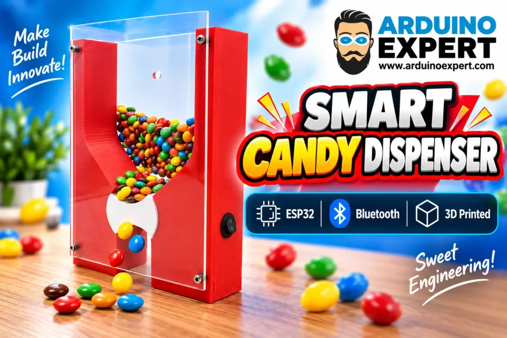
We designed and developed a custom automatic candy dispenser that combines Product Design and Development, Embedded Systems Development, custom electronics, 3D printing, and ESP32 programming in one complete functional prototype.
The project was developed from the ground up, including the mechanical enclosure, candy storage system, dispensing mechanism, electronic control circuit, Bluetooth communication, sensor integration, motor control, power system, firmware, and final assembly.
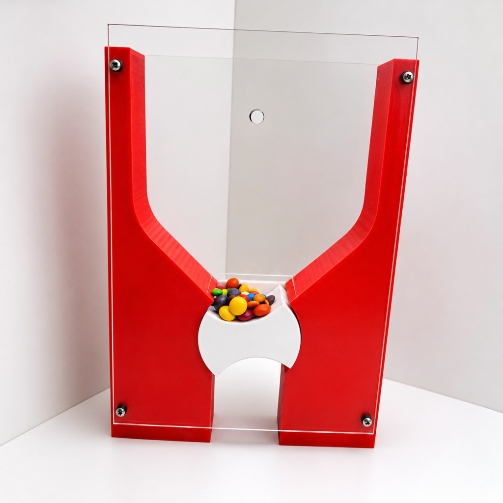
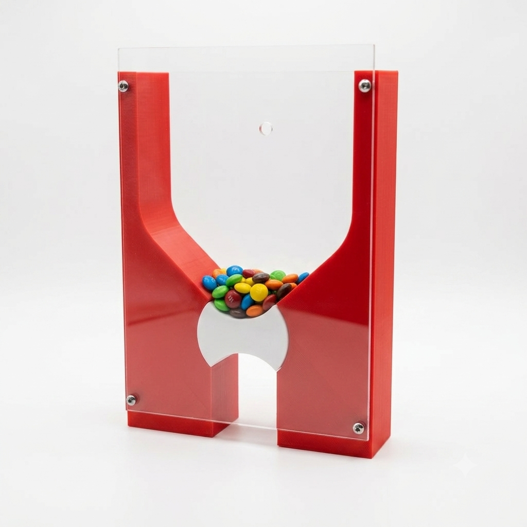
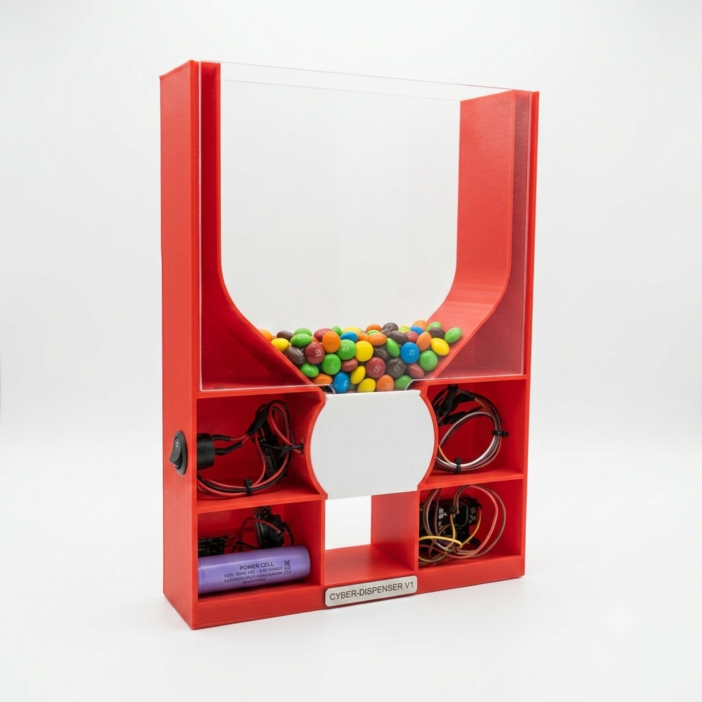
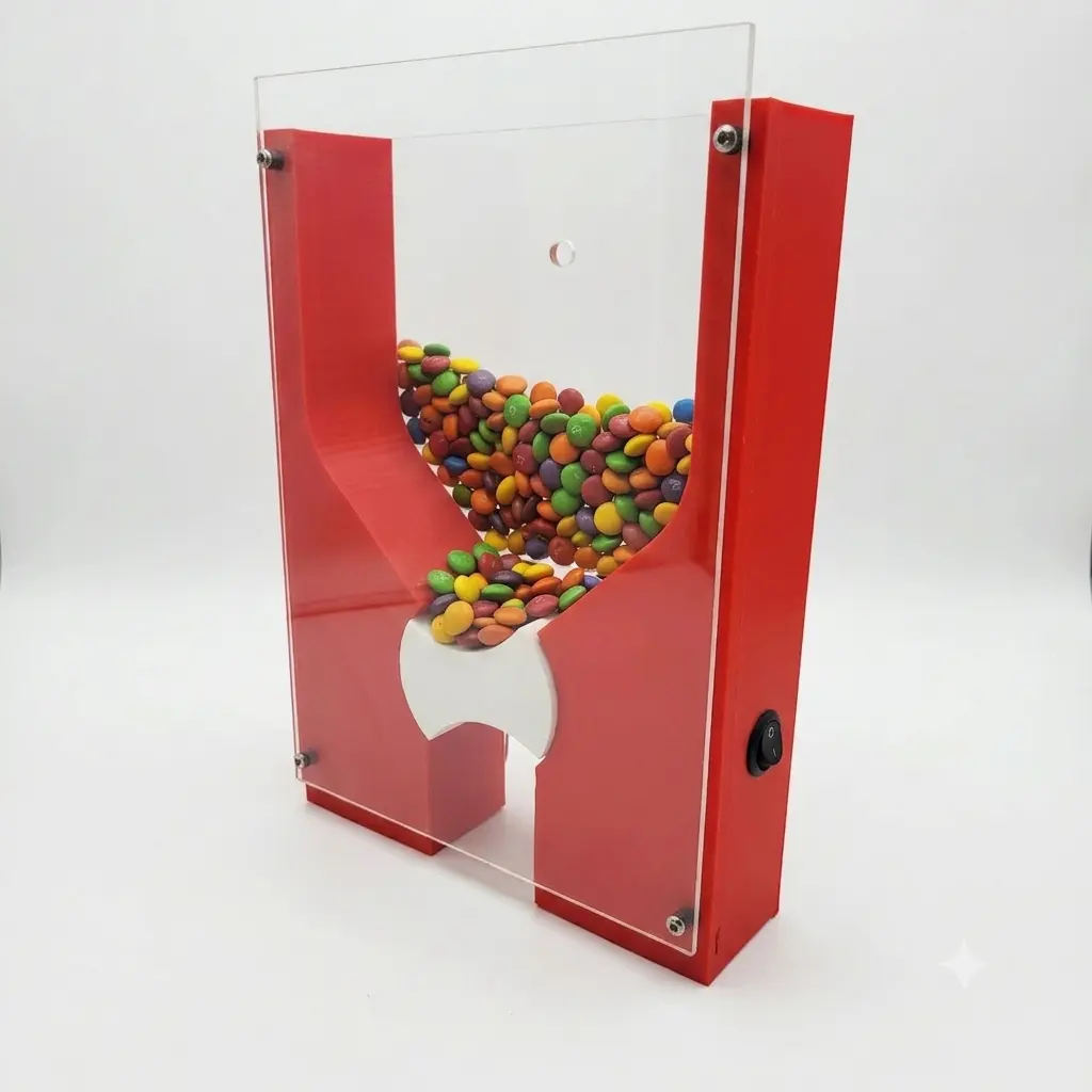
The body of the candy dispenser was 3D designed and 3D printed, while a transparent front cover was added to provide a clear view of the candies inside the storage chamber. The transparent panel also gives the product a clean and modern appearance while protecting the internal dispensing mechanism.
An ESP32 microcontroller acts as the main controller of the system. It receives commands through Bluetooth and operates a geared DC motor through a MOSFET motor control circuit. An IR sensor is used as part of the dispensing feedback system, while a buzzer provides audible status indication.
This project demonstrates how mechanical product design and custom electronics development can be combined to transform an idea into a working smart product prototype.
Candy Dispenser Project Overview
The objective of this project was to create a compact, rechargeable, and electronically controlled candy dispensing machine.
Instead of using a traditional manually operated candy dispenser, we developed a system in which the dispensing mechanism can be controlled electronically through an ESP32.
The project combines several engineering disciplines:
- Product Design and Development
- Mechanical CAD Design
- 3D Printing and Rapid Prototyping
- Arduino Project Development
- ESP32 Programming
- Embedded Systems Development
- Custom Electronics Project Development
- Bluetooth Control
- Sensor Integration
- DC Motor Control
- MOSFET Driver Circuit Design
- Rechargeable Battery Power System
- Prototype Assembly and Testing
The result is a complete functional prototype that demonstrates both the mechanical and electronic development process of a custom consumer product.
Custom Product Design and Development
One of the most important parts of this project was designing the physical structure of the candy dispenser.
The complete enclosure and candy storage system were designed specifically for this application rather than using an off-the-shelf enclosure.
The design needed to achieve several goals simultaneously:
- Store a useful quantity of candy
- Guide candies toward the dispensing mechanism using gravity
- Provide sufficient space for the motor and electronics
- Keep the product compact
- Allow easy loading of candies
- Provide visibility of the contents
- Protect moving mechanical components
- Allow the electronics to be installed cleanly inside the enclosure
- Create a product that could be manufactured using 3D printing
The final enclosure uses a vertical hopper-style layout. The internal geometry directs the candies toward the motorized dispensing section at the lower portion of the machine.
This makes the project an excellent example of practical Product Design and Development, where mechanical geometry, electronics, usability, manufacturing, and aesthetics must all work together.
3D Designed and 3D Printed Candy Dispenser
The body of the candy dispenser was created using 3D CAD design and manufactured through 3D printing.
3D printing was particularly useful for this project because it allowed us to rapidly prototype custom shapes for the candy hopper, motor mounting points, internal supports, outlet area, and electronics enclosure.
Using additive manufacturing also made it possible to modify the mechanical design during development without requiring expensive molds or conventional manufacturing tooling.
This type of workflow is ideal for:
Concept → CAD Design → 3D Print → Assembly → Testing → Design Improvement
Rapid prototyping significantly reduces development time when creating custom electronic products.
Transparent Front Cover Design
A transparent cover was installed on the front of the dispenser.
This panel serves both functional and aesthetic purposes.
The transparent cover allows users to immediately see the candies stored inside the machine while preventing the candies from falling out of the open hopper area.
It also protects the internal mechanism while retaining the visual appeal of a traditional candy dispensing machine.
The transparent front panel is mechanically attached to the 3D printed frame, creating a clean enclosed structure while maintaining visibility of the candy reservoir.
This combination of 3D printed structural components and transparent sheet material gives the prototype a more finished, product-like appearance.
Components Used for Candy Dispenser
| Component | Function |
|---|---|
| ESP32 | Main embedded controller |
| DC Gear Motor | Operates dispensing mechanism |
| MOSFET Module | Electronic motor driver/switch |
| IR Sensor | Dispensing detection and feedback |
| Buzzer | Audible status indication |
| 18650 Battery | Rechargeable power source |
| IP5306 Module | Battery charging and power management |
| Capacitor | Motor noise and voltage transient suppression |
| Power Switch | Main system power control |
| 3D Printed Enclosure | Mechanical body and candy hopper |
| Transparent Front Cover | Candy visibility and mechanical protection |
How the Automatic Candy Dispenser Works
When the device is powered on, the ESP32 initializes the Bluetooth communication and connected hardware.
A user can then send a dispensing command through a Bluetooth-enabled device.
The operating sequence is:
- The ESP32 receives the Bluetooth command.
- The firmware starts the dispensing sequence.
- The ESP32 sends a control signal to the MOSFET module.
- The MOSFET powers the DC geared motor.
- The motor rotates the candy dispensing mechanism.
- Candy moves from the storage hopper toward the outlet.
- The IR sensor provides feedback to the ESP32.
- The controller determines when the dispensing cycle has completed.
- The ESP32 switches off the motor.
- The buzzer provides audible feedback.
- The system returns to its waiting state for the next command.
This architecture makes the device a practical example of a sensor-based embedded control system.
ESP32-Based Embedded System
The main controller used in the project is an ESP32 microcontroller.
The ESP32 was selected because it provides significantly more functionality than a basic microcontroller while remaining compact and affordable.
It handles the primary embedded functions of the dispenser, including:
Bluetooth command → Processing → Motor activation → Sensor monitoring → Dispensing control → Buzzer feedback
The ESP32 provides built-in Bluetooth capability, eliminating the need for a separate Bluetooth communication module.
This makes the project a good practical example of Embedded Systems Development using ESP32.

Bluetooth/BLE-Controlled Candy Dispensing
Bluetooth communication allows the candy dispenser to receive commands wirelessly.
A phone, computer, or compatible Bluetooth application can communicate with the ESP32.
For example, when the ESP32 receives a dispensing command, the controller can activate the motor and begin the dispensing sequence.
The basic workflow is:
Bluetooth Device → ESP32 → MOSFET Motor Driver → DC Gear Motor → Candy Dispensed
After the dispensing operation is completed, the ESP32 can stop the motor and provide feedback through the buzzer or Bluetooth communication.
This wireless control capability transforms the device from a purely mechanical dispenser into a smart electronic candy dispenser.
DC Gear Motor Dispensing Mechanism
A DC geared motor is used to mechanically operate the candy dispensing mechanism.
A geared motor was chosen because candy dispensing requires torque at relatively low rotational speed rather than extremely high motor speed.
The gearing provides sufficient mechanical force to operate the dispensing section while allowing the controller to regulate the motor electronically.
The motor is not powered directly from the ESP32 GPIO because a microcontroller output cannot safely supply the current required by a DC motor.
Instead, the ESP32 controls the motor through a MOSFET driver circuit.
MOSFET Motor Control Circuit
A MOSFET module acts as the electronic power switch between the ESP32 and the DC motor.
The control architecture is approximately:
ESP32 GPIO → MOSFET Driver → DC Gear Motor
The ESP32 only supplies the low-current control signal, while the MOSFET handles the higher motor current.
This method offers several advantages:
- Efficient electronic switching
- Low power loss
- PWM motor control capability
- Reduced load on the ESP32
- Improved reliability
- Easy firmware control
IR Sensor for Candy Detection and Feedback
An IR sensor is integrated into the dispenser to provide feedback to the ESP32.
The sensor allows the embedded system to detect activity associated with the candy dispensing process and can be used to determine when the dispensing operation should stop.
Sensor feedback is important because operating a motor purely by timing is less reliable when mechanical conditions can change.
For example, candy position, quantity, friction, and mechanical resistance may vary between dispensing cycles.
Adding sensor feedback therefore improves the intelligence and reliability of the system.
Buzzer Status Indicator
A buzzer is included to provide audible feedback during operation.
The buzzer can be programmed for several functions, including:
- Dispensing indication
- Successful dispense confirmation
- Startup indication
- Error indication
- Jam warning
- Bluetooth command confirmation
Audible feedback improves the interaction between the user and the device, particularly when the dispenser is being operated remotely through Bluetooth.
Rechargeable 18650 Battery Power System
The dispenser is designed as a portable system and uses a rechargeable 18650 lithium-ion battery.
Rather than requiring a permanent wired power supply, the battery allows the device to be operated as a self-contained prototype.
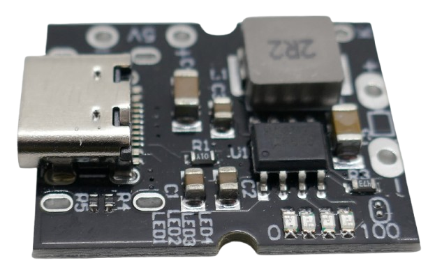
An IP5306 power management and boost module is incorporated into the power system.
The power module provides functionality associated with battery charging and regulated/boosted power delivery for the electronics.
The general power architecture is:
18650 Battery → IP5306 Power Module → ESP32 + Electronics + Motor Circuit
This approach makes the dispenser rechargeable and suitable for portable demonstrations.
Motor Noise Suppression and Power Stability
DC motors generate electrical noise because of their internal brushes and inductive characteristics.
This electrical noise can sometimes interfere with microcontrollers and other sensitive electronics.
To improve the stability of the candy dispenser, a capacitor was added at the motor input.
The capacitor helps suppress electrical noise and reduces short-duration voltage disturbances generated during motor operation.
Motor noise suppression is particularly important in embedded projects containing wireless communication because supply instability can potentially affect ESP32 operation or Bluetooth communication.
Circuit Diagram of Candy Dispenser with ESP32
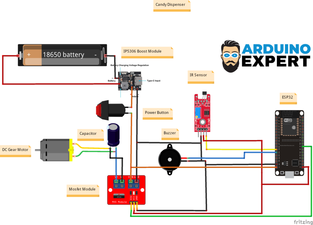
The ESP32 Smart Candy Dispenser Circuit Diagram represents the complete electrical architecture of the project, showing the connection between the power supply, microcontroller, motor control system, sensors, and output devices.
ESP32 Code for Smart Candy Dispenser
#include <BluetoothSerial.h>
#include <math.h>

BluetoothSerial SerialBT;

// ===========================
// PWM Configuration
// ===========================

const int PWM_CHANNEL = 0;
const int PWM_FREQ = 500;
const int PWM_RESOLUTION = 8;
const int MOTOR_PIN = 18;
const int BUZZER_PIN = 26;

bool MagnetState, Allow = false;
int currentDuty = 128;

// Process control
bool isRunning = false;
unsigned long startTime = 0;
unsigned long lastBuzzerToggle = 0;
bool buzzerState = false;

void setup()
{
    Serial.begin(115200);

    SerialBT.begin("Candy_Dispenser_BT");

    Serial.println("Bluetooth started. Pair and connect.");
    Serial.println("Send a number (0-100) to set PWM.");

    pinMode(25, INPUT);
    pinMode(MOTOR_PIN, OUTPUT);
    pinMode(BUZZER_PIN, OUTPUT);

    digitalWrite(BUZZER_PIN, LOW);
}

void loop()
{
Complete Custom Electronics Project Development
This candy dispenser represents more than an individual Arduino experiment.
It is an example of a complete Custom Electronics Project Development workflow.
The project required integration of:
Mechanical Design + Electronics + Embedded Firmware + Power Management + Sensors + Motor Control + 3D Printing
Developing these systems together is important because changes in one area frequently affect another.
For example, the motor determines mechanical torque requirements, power consumption affects battery selection, sensor placement depends on enclosure geometry, and PCB/electronics dimensions affect the mechanical enclosure.
This multidisciplinary workflow is an essential part of professional Product Design and Development.
Software and Embedded Systems Development
The embedded firmware connects the physical product with its electronic control system.
This project demonstrates several important embedded programming concepts:
- GPIO control
- Digital sensor input
- Motor switching
- PWM concepts
- Bluetooth serial communication
- State-based control
- Timing using microcontroller functions
- Actuator control
- Sensor feedback
- Error handling
- Hardware/software integration
Because the software directly interacts with physical hardware, careful testing is required to account for real-world events such as motor stalls, candy jams, sensor noise, communication interruptions, and changing battery voltage.
Product Development Challenges
A product such as an automatic candy dispenser may look simple from the outside, but several engineering challenges must be solved during development.
Candy Flow
Candies can stack together and create bridging near narrow openings. Hopper geometry therefore has to encourage consistent movement toward the dispenser.
Motor Torque
The motor requires enough torque to move the dispensing mechanism even when candies create mechanical resistance.
Motor Current
The electronics must tolerate both normal motor current and the higher startup current generated when the motor begins rotating.
Sensor Reliability
The IR sensor must be positioned correctly so that it detects the required dispensing event without false triggering.
Electrical Noise
Brush noise and motor switching can create interference, making motor suppression and good power design important.
Mechanical Tolerances
The 3D printed moving components require suitable clearances so they can rotate freely without allowing excessive candy movement.
Addressing these challenges is what transforms a concept into a practical working prototype.
Applications of This Candy Dispenser
Although this prototype is designed for candy dispensing, the underlying technology can be adapted for many other automatic dispensing systems.
Possible applications include:
- Snack dispensing machines
- Pet food dispensers
- Tablet or pill dispensing prototypes
- Seed dispensers
- Small component feeders
- Promotional product dispensers
- Token dispensers
- Educational vending machine projects
- Portion-controlled dispensing systems
- Smart retail demonstration products
The same electronics and embedded control architecture can be modified depending on the required dispensing mechanism.
Related Projects
Below you can find the our similar projects.
- Powder Dispenser Machine with Touch LCD Control and Arduino
- Juice Dispenser Machine with Arduino Mega
- Smart and Automatic Perfume Atomizer/Dispenser with Arduino
- Smart Sanitizer Dispenser Using Arduino
- IoT Smart Pill Dispenser & Medicine Reminder System using Arduino UNO R4 WiFi
Conclusion
The ESP32 Smart Candy Dispenser project successfully demonstrates the complete process of transforming an idea into a functional smart product through Product Design and Development, Embedded Systems Development, Custom Electronics Project Development, and Rapid Prototyping.
The project combines mechanical design, 3D printing, electronics, firmware programming, and automation into a single integrated system. The candy dispenser enclosure and internal structure were custom designed and 3D printed, while the transparent front cover enhanced both the visual appeal and usability of the final prototype by allowing users to view the candy storage area.
Need a Custom Candy Dispenser?
Looking for a custom candy dispenser designed specifically for your idea or business requirement? We can help transform your concept into a fully functional smart product.
Our team specializes in Product Design and Development, Custom Electronics Project Development, Embedded Systems Development, 3D CAD Design, 3D Printing, and prototype manufacturing. From mechanical design and dispensing mechanisms to electronics integration, firmware development, sensors, motors, and wireless control, we provide complete end-to-end development support.
Frequently Asked Quetions
What is an ESP32 automatic candy dispenser?
An ESP32 automatic candy dispenser is an electronically controlled dispensing system in which an ESP32 microcontroller operates a mechanical candy dispensing mechanism. In this project, the ESP32 communicates through Bluetooth and controls a DC geared motor through a MOSFET circuit.
Was the candy dispenser custom designed?
Yes. The dispenser body, candy storage section, structural components, and mechanical arrangement were custom designed as part of the Product Design and Development process.
Is the candy dispenser 3D printed?
Yes. The main physical structure was designed using 3D CAD techniques and manufactured through 3D printing. This allowed rapid prototyping and easy modification of the enclosure and mechanical components.
Why does the candy dispenser have a transparent front cover
The transparent front panel allows users to see the candy level while keeping the candies and internal mechanism protected. It also improves the appearance of the finished prototype.
How is the candy dispenser controlled?
The ESP32 receives commands through Bluetooth. After receiving the appropriate command, it controls the MOSFET motor driver and activates the DC geared motor to operate the dispensing mechanism.
Why is a MOSFET used with the motor?
The ESP32 cannot directly supply the current required by a DC motor. A MOSFET allows the low-current ESP32 control signal to switch the higher motor current efficiently and safely.
Why is a capacitor used with the motor?
A DC motor can generate electrical noise and brief voltage disturbances. The capacitor helps suppress motor noise and improves power stability for the ESP32 and other electronics.
Can this design be adapted for other dispensing applications?
Yes. The same concept can be adapted for products such as snack dispensers, pet food dispensers, component feeders, token dispensers, seed dispensers, or other small automated dispensing systems by modifying the mechanical mechanism and firmware.
Can you modify this candy dispenser or make a custom candy dispenser?
Yes we can modify or can develop a custom candy dispenser as per you need.