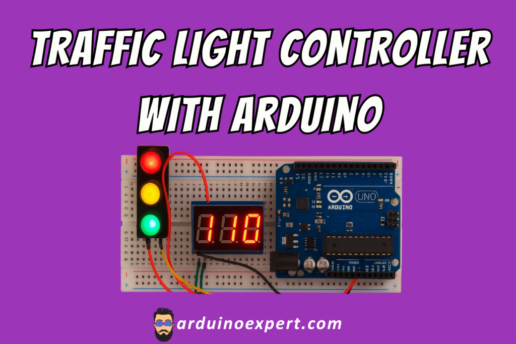
Traffic signals are one of the most important systems in modern transportation. In this project, we will build a Traffic Light Controller with Arduino UNO, using a LED Traffic Light Module, a TM1637 7-Segment Display Module, and a simple breadboard setup. This project simulates a real-world traffic signal system while displaying the countdown timer on a digital display.
This is a great beginner-friendly Arduino project for students, makers, hobbyists, and anyone learning embedded systems, electronics, and IoT concepts. We’ve also uploaded the working video/short of this project on our YouTube channel, where you can see the entire system in action.
Project Overview: Traffic Light Controller
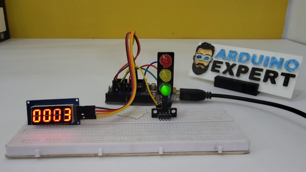
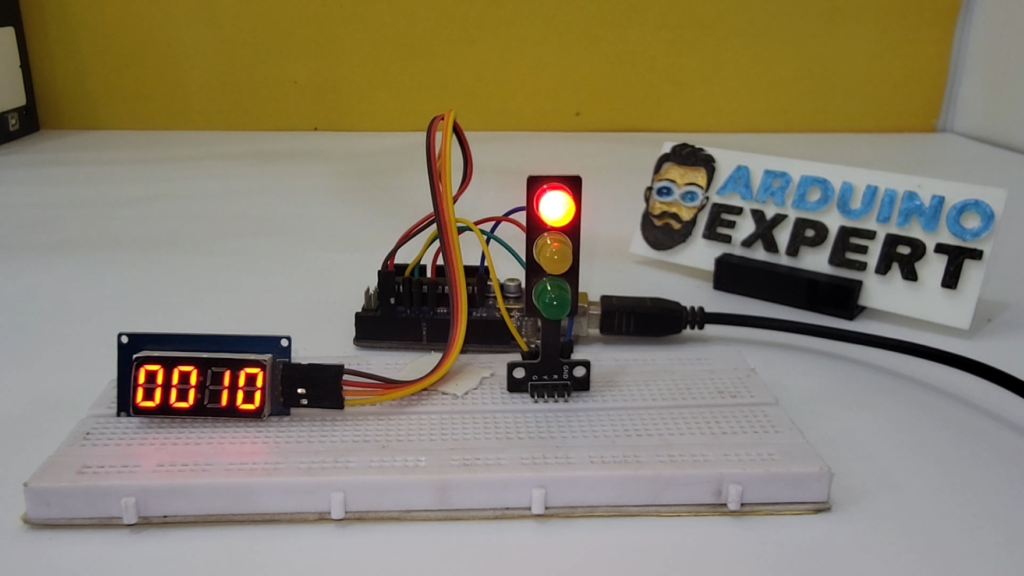
In this Arduino-based Traffic Light Controller, three LEDs (Red, Yellow, and Green) are used to represent a traffic signal. Along with the lights, we use a TM1637 7-segment display to show a countdown timer so users can see how much time is left before the light changes.
The system follows a real-world sequence:
- Red LED ON → Stop
- Yellow LED ON → Get Ready
- Green LED ON → Go
The countdown timer changes dynamically for each color, making it a perfect simulation of an actual traffic light controller.
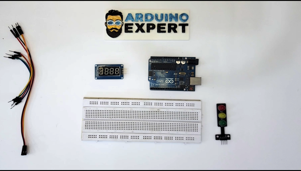
Components Used in Traffic Light Controller:
| Component | Quantity | Description |
|---|---|---|
| Arduino UNO | 1 | Main microcontroller |
| LED Traffic Light Module | 1 | Contains Red, Yellow, Green LEDs |
| TM1637 7-Segment Display | 1 | Shows countdown timer |
| Breadboard | 1 | For wiring |
| Jumper Wires | As needed | Connections |
| USB Cable | 1 | To upload code |
Why This Project Is Useful?
- Helps beginners understand Arduino programming
- Demonstrates the concept of timing and LED control
- Realistic simulation of traffic management systems
- Can be extended into an advanced IoT traffic control project
- Lightweight and low-cost DIY electronics project
This project is ideal for school projects, engineering assignments, YouTube tutorials, and learning platforms.
Working Principle of Traffic Light Controller
The Arduino sends signals to the LED Traffic Light Module based on predefined delay intervals. For each light duration, the TM1637 display shows a countdown starting from the set value.
Example Timing Sequence:
- Red Light → 10 seconds
- Green Light → 8 seconds
- Yellow Light → 3 seconds
The Arduino updates the 7-segment display every second, giving a clear view of the remaining time before the next signal change.

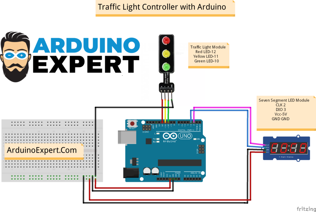
Circuit Diagram of Traffic Light Controller with Arduino
- LED Traffic Light Module
- Red, Yellow, and Green LEDs are connected to Arduino digital pins.
- TM1637 Display
- Connected using CLK and DIO pins to Arduino
- Arduino UNO
- Controls the LEDs and the countdown logic
The wiring is simple because the TM1637 display only requires 2 pins, making it easier for beginners.
Arduino Code for Traffic Light Controller Project
#include <TM1637Display.h>

// TM1637 Pins
#define CLK 2
#define DIO 3

TM1637Display display(CLK, DIO);

// Traffic Light LED Pins
#define RED_LED 12
#define YELLOW_LED 11
#define GREEN_LED 10

// Light durations (seconds)
int redTime = 10;
int greenTime = 8;
int yellowTime = 3;

void setup() {
  // LED Pin Modes
  pinMode(RED_LED, OUTPUT);
  pinMode(YELLOW_LED, OUTPUT);
  pinMode(GREEN_LED, OUTPUT);

  // Initialize Display
  display.setBrightness(7); // 0-7 brightness level
}

void loop() {

  // ---------------- RED LIGHT ----------------
  digitalWrite(RED_LED, HIGH);
  countdown(redTime);
  digitalWrite(RED_LED, LOW);

  // ---------------- GREEN LIGHT ----------------
  digitalWrite(GREEN_LED, HIGH);
  countdown(greenTime);
  digitalWrite(GREEN_LED, LOW);

  // ---------------- YELLOW LIGHT ----------------
  digitalWrite(YELLOW_LED, HIGH);
  countdown(yellowTime);
  digitalWrite(YELLOW_LED, LOW);
}

// FUNCTION: Show countdown on TM1637
void countdown(int timeInSeconds) {
  for (int i = timeInSeconds; i >= 0; i--) {
    display.showNumberDec(i);
    delay(1000);
  }
}
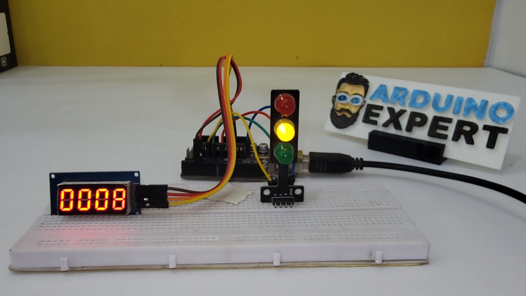
Project Setup: Traffic Light Controller
Working Video of Traffic Light Controller Project
Applications of Traffic Light Controller Project
This project can be used in:
- Engineering Lab Experiments
- Mini Projects for Electronics Students
- School Demonstrations
- Traffic System Simulations
- Smart City & IoT Learning
- Real-World Prototype of Traffic Controller
Conclusion
The Traffic Light Controller with Arduino UNO is a perfect hands-on project for learning about microcontrollers, electronics, timing logic, and display modules. With the addition of the TM1637 7-segment display, the system becomes realistic and highly interactive.
Don’t forget to check out the working video/short on our YouTube channel, where we show the complete demonstration of the traffic light sequence and countdown timer.
This project is an excellent addition to your Arduino Projects Portfolio and can be further expanded using sensors, IoT platforms, or wireless communication.
Need Help/Assistance in Arduino Traffic Light Controller Project?
If you need this IoT Smart Door Lock Project System with or without Modifications or Customization then you can contact us through WhatsApp.
Learn More about the services we offer