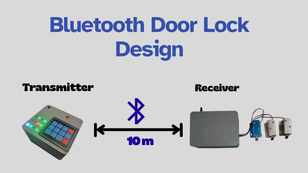
At Arduino Expert, we specialize in Product Design and Development using embedded systems, automation, and IoT-based technologies. One of our remarkable Arduino Projects is the Bluetooth Door Lock System, developed for a client who required a secure, wireless, and efficient way to control multiple locks remotely.
This project represents a perfect blend of Arduino Programming, Bluetooth communication, and 3D Design and Modeling, integrating hardware, firmware, and mechanical design into a single cohesive system.
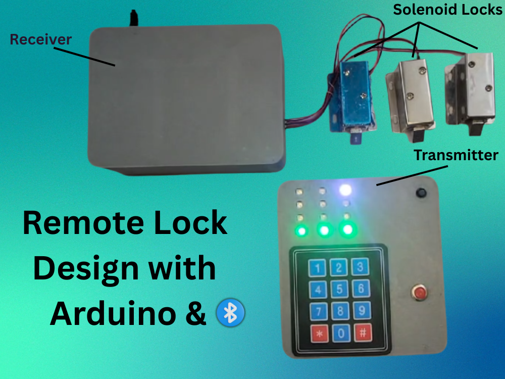
The Bluetooth Door Lock System consists of two Arduino microcontrollers—one placed at the locker side and the other at the keypad side. Both Arduinos communicate wirelessly using HC-05 Bluetooth modules, creating a reliable and responsive smart locking mechanism.
The locker side houses the solenoid locks and relay system, while the keypad side serves as the user interface with a keypad, LED indicators, and control buttons. The system provides visual LED feedback, password-based security, and intuitive lock selection—all powered by a custom 3D-printed design developed entirely in-house by Arduino Expert.
Hardware Overview of Bluetooth Door Lock System
1. Components used on Locker Side (Receiver Unit)
The locker side of this Arduino Project is based on Arduino Uno, responsible for controlling the solenoid locks through relay switching.
Key components include:
- Arduino Uno
- HC-05 Bluetooth Module
- 4-Channel Relay Module
- Three Solenoid Locks
- 12V DC External Power Supply
Each solenoid lock is individually controlled by the Arduino Uno, which receives open/close commands via Bluetooth from the keypad unit.
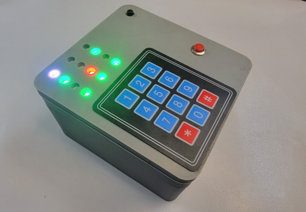
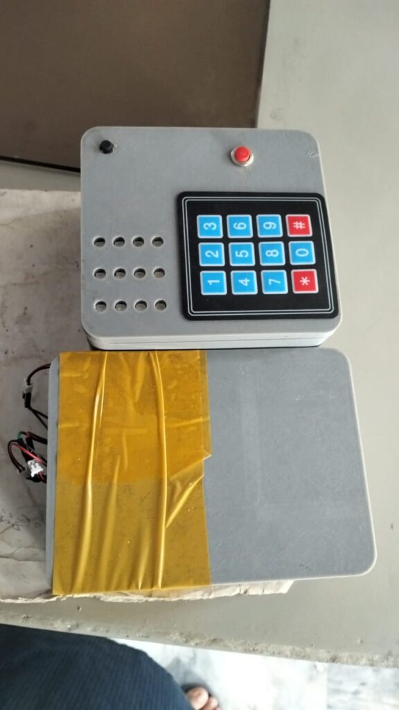
2. Components used on Keypad Side (Transmitter Unit)
The keypad side is powered by Arduino Mega, providing sufficient input/output handling for the peripherals.
Key components include:
- Arduino Mega 2560
- 4×3 Matrix Keypad
- Three WS2812B LED Strips (4 LEDs per strip)
- Push Button (for lock selection)
- Voltage Sensor (for battery monitoring)
- HC-05 Bluetooth Module
- Two 18650 Li-ion Cells with Charging Circuit
- Power On/Off Switch
This side acts as the control panel for the user, allowing lock selection, password entry, and visual feedback through LED strips. It runs entirely on rechargeable batteries, offering portable and wireless operation.
System Functionality of Bluetooth Door Lock System
The system operates seamlessly through Bluetooth communication between the keypad side and the locker side, performing various functions in a synchronized manner.
1. System Initialization
When both Arduinos establish a Bluetooth connection, the first LED on each of the three WS2812B strips glows green, indicating a successful connection and system readiness.
2. Lock Selection
Pressing the push button cycles through the available locks (Lock 1, Lock 2, Lock 3).
- The second LED of the respective LED strip lights up, signaling which lock is currently selected for operation.
3. Password Entry and Verification
Once a lock is selected, the user enters its specific password on the keypad.
- If the correct password is entered and confirmed using the hash (#) button, the third LED turns green, and the corresponding solenoid lock on the locker side unlocks.
- If an incorrect password is entered, the fourth LED of the respective strip lights up red, alerting the user of an invalid attempt.
4. Universal Lock Reset
Pressing the asterisk (*) button resets all locks to their default closed state, ensuring maximum security. The user must re-enter the correct password to reopen any lock.
5. Power Management
The keypad side is battery-powered, equipped with dual 18650 cells and a charging module for continuous usability. A voltage sensor continuously monitors battery health, while an on/off switch allows manual power control. The locker side uses a 12V power supply to ensure reliable solenoid operation.
Circuit Diagram of Bluetooth Door Lock with Arduino
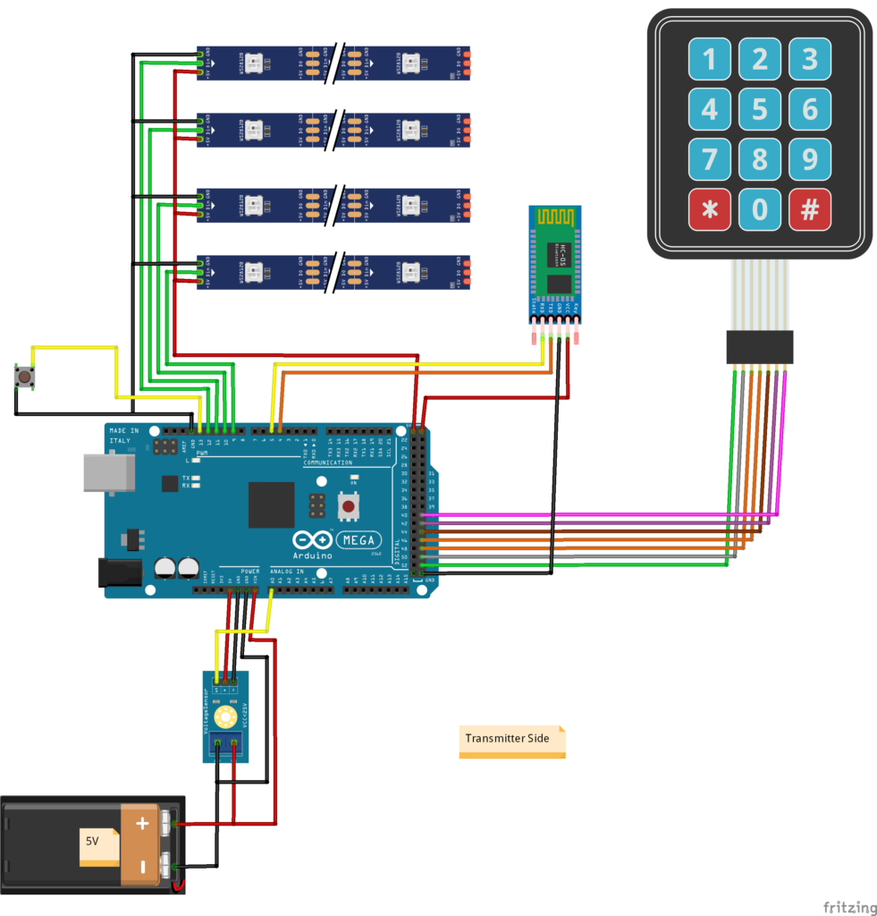
1. Circuit Diagram of Bluetooth Door Lock with Arduino (Keypad-Transmitter Side)
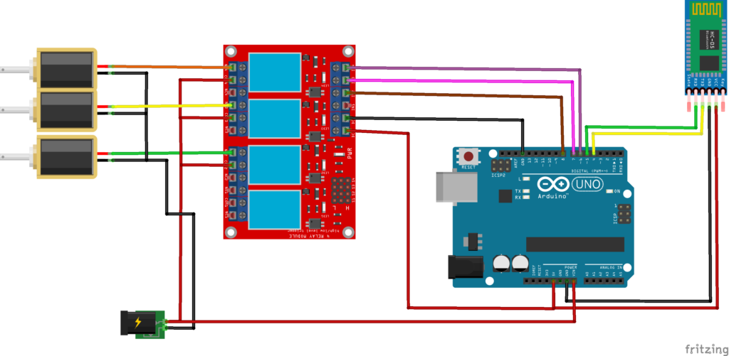
2. Circuit Diagram of Bluetooth Door Lock with Arduino (Receiver Side-Locker Side)
Arduino Code for Bluetooth Door Lock (Keypad Side-Transmitter Side)
#include <Keypad.h>
#include <Adafruit_NeoPixel.h>
#include <SoftwareSerial.h>
SoftwareSerial bluetoothSerial(7, 8);  // RX, TX

const byte ROWS = 4;  // Four rows
const byte COLS = 3;  // Three columns

char keys[ROWS][COLS] = {
  { '1', '2', '3' },
  { '4', '5', '6' },
  { '7', '8', '9' },
  { '*', '0', '#' }
};

byte rowPins[ROWS] = {A2, A1, 2, 3}; //connect to the row pinouts of the keypad
byte colPins[COLS] = {4, 5, 6}; //connect to the column pinouts of the keypad


// Create an object of Keypad
Keypad keypad(makeKeymap(keys), rowPins, colPins, ROWS, COLS);

// Define the number of pixels and pins for each LED strip
#define NUM_PIXELS 3    // Number of pixels per strip
#define PIN_STRIP_1 12  // Pin for the first LED strip
#define PIN_STRIP_2 11  // Pin for the second LED strip
#define PIN_STRIP_3 10  // Pin for the third LED strip
#define PIN_STRIP_4 9  // Pin for the fourth LED strip

// Define the pin for the button
#define BUTTON_PIN 13

// Define passcodes
const char* passcode1 = "123";
const char* passcode2 = "456";
const char* passcode3 = "789";

int ResultPass1 = 0, ResultPass2 = 0, ResultPass3 = 0;

int Lock_Index = 1;
// Add this boolean flag
bool keysEntered = false;
bool latch = true;

// Variables to store current passcode being entered
String currentPasscode = "";
String TargetPasscode = passcode1;
Arduino Code for Bluetooth Door Lock (Receiver Side-Locker Side)
#include <SoftwareSerial.h>

SoftwareSerial bluetoothSerial(7, 8);  // RX, TX

// Define pin numbers for relays
const int relayPin1 = 4;
const int relayPin2 = 5;
const int relayPin3 = 6;

void setup() {
  Serial.begin(9600);
  bluetoothSerial.begin(9600);  // Initialize Bluetooth serial communication

  // Initialize relay pins as outputs
  pinMode(relayPin1, OUTPUT);
  pinMode(relayPin2, OUTPUT);
  pinMode(relayPin3, OUTPUT);

  // Initially, turn off all relays
  digitalWrite(relayPin1, HIGH);
  digitalWrite(relayPin2, HIGH);
  digitalWrite(relayPin3, HIGH);
}
3D Design and Modeling of Casing of Bluetooth Door Lock
As part of our Product Design and Development services, our team at Arduino Expert designed custom 3D-printed enclosures for both the keypad unit and locker unit. Using advanced 3D Design and Modeling software, we created compact, ergonomic, and professional-looking casings that ensure:
- Proper component placement and ventilation
- Secure mounting of all modules and wires
- Ease of assembly and maintenance
- Visually appealing aesthetics for client presentation
Both enclosures were fabricated using in-house 3D printers, ensuring accuracy and build quality.
Testing and Validation of Door Lock System
After completing hardware assembly and programming, the entire system underwent a series of rigorous functional and performance tests. The tests confirmed:
- Reliable Bluetooth connectivity
- Accurate lock control response
- Correct LED indication for each operation
- Stable power performance and safety under extended use
After thorough testing, the fully assembled and functional system was delivered to the client.
Working Video of Bluetooth Door Lock System
We also showcased a demonstration video of the project on our official YouTube channel — Arduino Expert, highlighting its working principles and features.
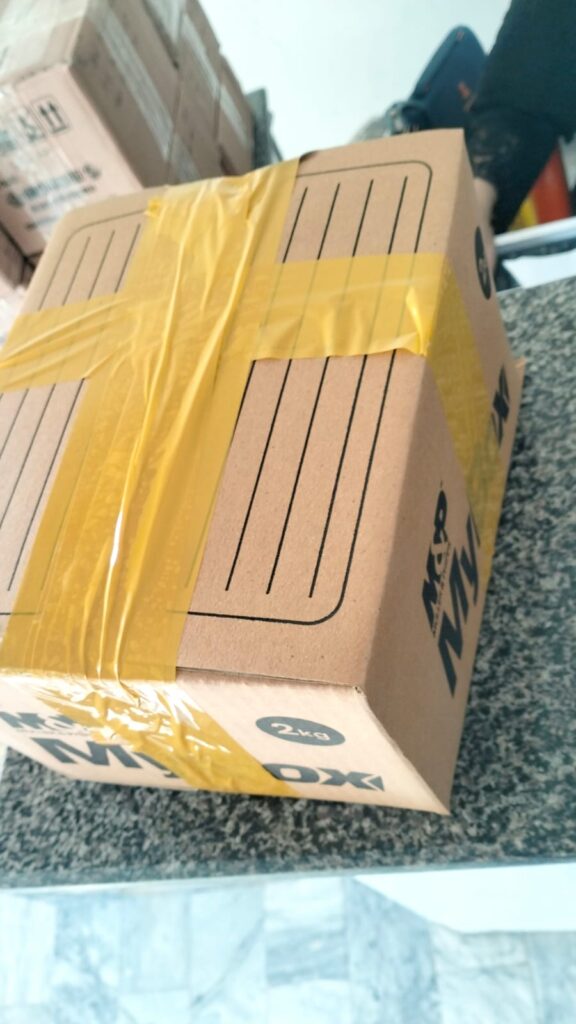
Packaging and Shipment of Bluetooth Door Lock Project to Client
Applications of Bluetooth Door Lock System
This Bluetooth Door Lock System can be adapted for a variety of real-world applications, including:
- Smart Lockers in schools, offices, and gyms
- Secure Storage Cabinets for tools, equipment, or documents
- Home and Office Automation systems
- Hotel Room Lockers with remote access
- Prototype systems for research and training in Arduino Programming and IoT Security Projects
The system offers an ideal combination of electronic control, mechanical locking, and Bluetooth technology — a perfect educational and practical example for Arduino enthusiasts and product developers.
Conclusion
The Bluetooth Door Lock with Arduino project developed by Arduino Expert demonstrates our capability in end-to-end product design and development, combining Arduino Programming, Bluetooth communication, and 3D Design and Modeling into a functional, reliable, and user-friendly solution.
From circuit design and code development to mechanical modeling, 3D printing, and final testing — every phase was executed with precision and expertise. The project was successfully delivered to the client as a ready-to-use, fully operational smart locking system, representing another milestone in our portfolio of advanced Arduino Projects.
Our approach reflects our core philosophy — turning innovative ideas into real, working products through professional design, engineering, and creativity.
Need IoT Bluetooth Door Lock System Project?
If you need this Bluetooth Door Lock with Arduino System with or without Modifications or Customization then you can contact us through WhatsApp. We can deliver you the Fully Functional Project with Hardware/Components Shipment:
if you can not make this project yourself then you can use this option. We will assemble the Project and will ship it to your Doorstep with Safe Packaging.
Learn More about the services we offer.