In today’s world of smart electronics and health-focused technology, real-time health monitoring systems are becoming increasingly important. One of the most popular and practical applications in this domain is a heart rate monitoring system.
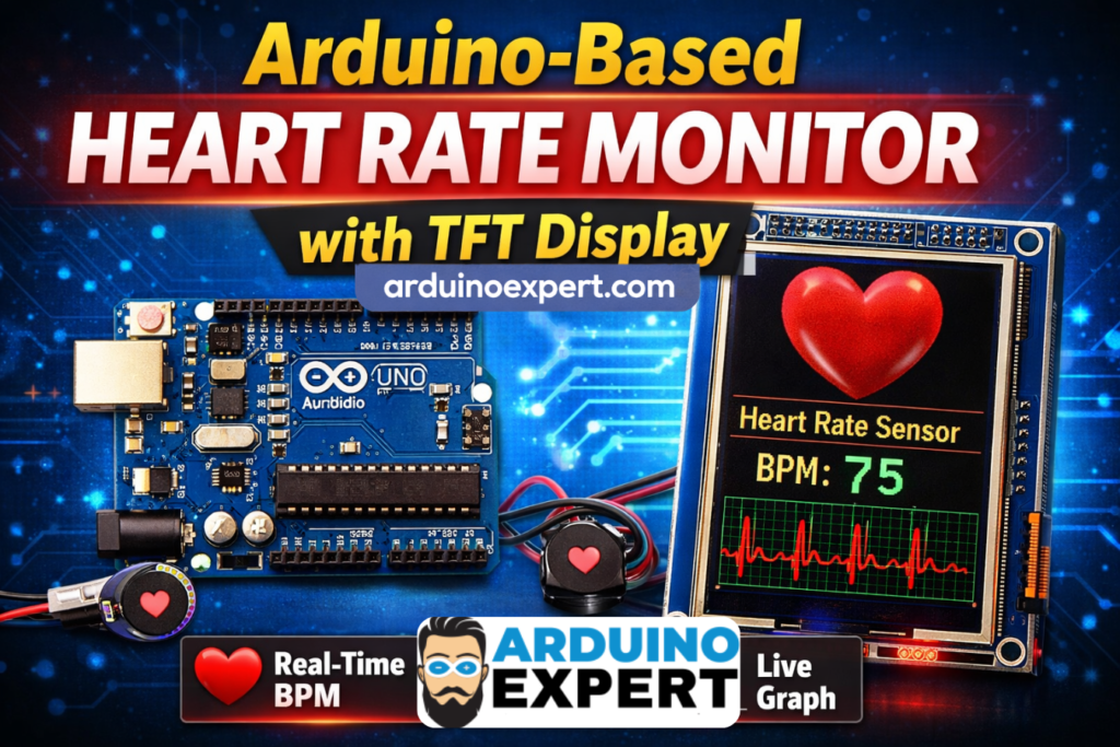
In this project, we have developed an Arduino-based real-time heart rate monitoring system with TFT display, capable of accurately detecting pulse signals and displaying live BPM (Beats Per Minute) along with a visual waveform. This system integrates a pulse sensor, Arduino microcontroller, TFT LCD display, and SD card module to create a complete embedded solution.
Unlike basic pulse sensor projects, this system goes a step further by offering:
- Real-time graphical visualization
- Accurate BPM calculation using interrupt-based logic
- User-friendly TFT interface
- Startup image display via SD card
Components Required for Real-Time TFT LCD Heart Rate Monitoring System
- Arduino Uno / Mega
- Pulse Sensor (Heart Rate Sensor)
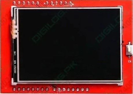
- TFT LCD Display (ILI9341 or similar)
- SD Card Module
- Micro SD Card (with BMP image)
- Connecting wires
- Breadboard
- Power supply
Checkout Our Similar Project: Smart Heart Rate Display System Using Adafruit FLORA and NeoPixel LEDs
LCD Display Heart Rate Monitoring System Overview
This system works by continuously reading analog signals from the pulse sensor, processing the signal to detect heartbeats, and calculating the BPM (Beats Per Minute).
The processed data is then displayed on a TFT LCD screen, along with a real-time waveform graph that visually represents the heartbeat signal.
How the Heart Rate Monitoring System Works
1. Pulse Signal Acquisition
The pulse sensor is connected to an analog pin of Arduino (e.g., A5). It detects blood flow changes and converts them into electrical signals.
2. Interrupt-Based Sampling
The system uses a timer interrupt to sample data every 2 milliseconds, ensuring accurate and consistent readings.
3. Heartbeat Detection Algorithm
- Detects peaks and troughs in the signal
- Calculates time between beats (IBI)
- Converts IBI into BPM using formula:
BPM=60000IBIBPM = \frac{60000}{IBI}BPM=IBI60000
4. TFT Display Output
The TFT screen displays:
- Heart rate (BPM)
- Live waveform graph
- System labels and UI elements
5. SD Card Image Display
On startup, a heart image (BMP format) is loaded from the SD card and displayed on the screen.
If you want to make CPAP Mask Pressure Monitoring Device then Checkout our CPAP Device Project
Features of Smart Heart Rate Monitoring System Project
- Real-time heart rate monitoring
- Accurate BPM calculation
- Live waveform visualization
- TFT graphical interface
- Interrupt-based signal processing
- SD card image display
- LED heartbeat indicator
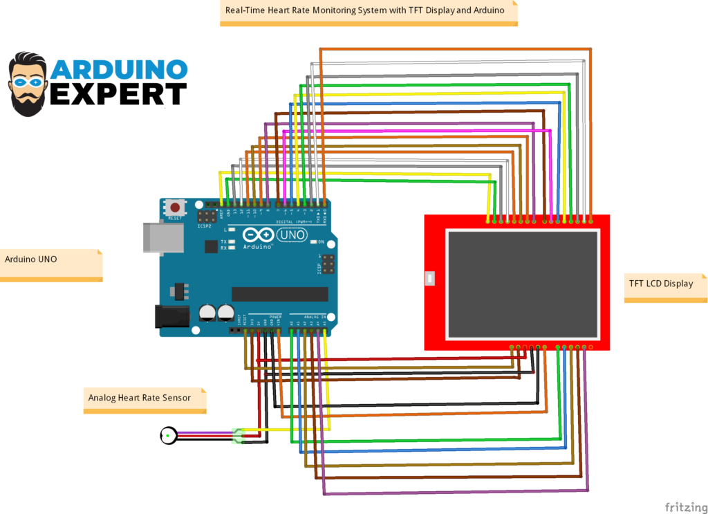
Circuit Diagram of Arduino with TFT LCD and Analog Heart Rate Sensor
Arduino Code for Custom Heart Rate Monitoring System with TFT Interface
#include <UTFTGLUE.h> // Include the GLUE class and constructor

const int bufferSize = 100; // Size of the circular buffer
int heartRates[bufferSize]; // Circular buffer to store heart rate values
int currentIndex = 0; // Index to keep track of the current position in the circular buffer

UTFTGLUE myGLCD(0, A2, A1, A3, A4, A0); // Initialize the GLUE class with dummy arguments

//  Variables
const int PulseWire = A5;       // PulseSensor PURPLE WIRE connected to ANALOG PIN 0
const int LED = LED_BUILTIN;          // The on-board Arduino LED, close to PIN 13.
int Threshold = 550;

PulseSensorPlayground pulseSensor;

void setup() {
  // Initialize the LCD
  myGLCD.InitLCD();
  myGLCD.clrScr();

  // Set font and color
  myGLCD.setColor(255, 255, 255); // Set text color to white
  myGLCD.setFont(BigFont);        // Use a predefined font (assuming BigFont is available)

  // Display "Heart Rate Sensor" at the top left corner
  myGLCD.print("Heart Rate Sensor", 0, 0);

  // Display the static BPM text
  myGLCD.print("BPM=   ", RIGHT, myGLCD.getDisplayYSize() - 16); // Static position for BPM text, adjusted down by 16 pixels

  // Configure the PulseSensor object, by assigning our variables to it.
  pulseSensor.analogInput(PulseWire);
  pulseSensor.blinkOnPulse(LED);       //auto-magically blink Arduino's LED with heartbeat.
  pulseSensor.setThreshold(Threshold);

  // Double-check the "pulseSensor" object was created and "began" seeing a signal.
   if (pulseSensor.begin()) {
    Serial.println("We created a pulseSensor Object !");  //This prints one time at Arduino power-up,  or on Arduino reset.
  }
Code Functionality Overview
The Arduino code is structured into:
- Setup Function
- Initializes TFT display
- Loads image from SD card
- Configures interrupt timer
- Loop Function
- Updates display when heartbeat is detected
- Prints BPM values
- Interrupt Service Routine (ISR)
- Reads sensor data
- Detects heartbeat
- Updates BPM calculation
Applications of Heart Rate Monitoring System
This project has a wide range of real-world applications:
Healthcare Devices
- Patient monitoring systems
- Portable heart rate monitors
- Fitness tracking devices
Fitness & Sports
- Workout monitoring
- Athlete performance tracking
- Smart gym systems
Home Automation & IoT
- Health-based alert systems
- Smart wearable devices
Checkout Our IOT Heart Rate Monitoring using Arduino and Smartphone App
Educational Projects
- Engineering final year projects
- Embedded systems learning
- Arduino-based research work
Our Services
At ArduinoExpert.com, we provide professional services in:
- Custom Arduino Project Development
- Embedded Systems Design
- IoT Product Development
- PCB Design & Prototyping
- AI & Automation Solutions
If you need a custom health monitoring system or any embedded solution, feel free to contact us.
Conclusion
This Arduino-based heart rate monitoring system with TFT display is a powerful combination of electronics, signal processing, and embedded systems design. It not only demonstrates how to measure heart rate but also how to present data in a professional and interactive way.
Whether you are a student, hobbyist, or business looking for custom embedded solutions, this project showcases the potential of Arduino in healthcare technology.
Need Help in this Project?
If you want:
- Full project files
- Custom modifications
- Commercial product development
→ You can contact us through WhatsApp. We can deliver you this Project to your Doorstep with Safe Packaging or we can also provide you assistance for this project.
FAQs (Frequently Asked Questions)?
What is a heart rate monitoring system using Arduino?
It is a system that uses a pulse sensor and Arduino to measure and display heart rate in BPM.
How accurate is the Arduino pulse sensor?
It provides reasonably accurate results for educational and prototype purposes but is not a medical-grade device.
Can I use this project for commercial purposes?
Yes, with proper optimization and calibration, it can be developed into a commercial product.
Why is TFT display used in this project?
The TFT display provides a graphical interface to show BPM and waveform, making the system more user-friendly.
What is BPM in heart rate monitoring?
BPM stands for Beats Per Minute, which indicates the number of heartbeats in one minute.
Can this project be converted into an IoT system?
Yes, by adding WiFi modules like ESP8266 or ESP32, you can send data to cloud platforms.