Security systems have become essential elements in modern Product Design and Development, particularly in smart gadgets and electronic access control solutions. Traditional mechanical locks, though widely used, lack flexibility, monitoring, and digital intelligence. To overcome these limitations, designers and engineers often turn to microcontroller-based solutions that offer higher reliability, programmability, and custom features.
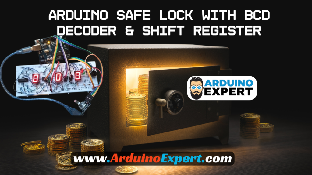
The Smart Safe Lock System using Arduino is a compact yet powerful security device designed using the Arduino Programming Language and commonly available electronic components. At the heart of the system is the Arduino UNO, which controls user input, password verification, display output, memory retention, and alert signals. The user interacts with the system using a rotary encoder, allowing the selection and modification of a 3-digit password without the need for a large keypad.
The system uses three seven-segment displays driven by two shift registers (74HC595) and a BCD decoder, enabling efficient multiplexing and accurate visual feedback. The password, number of remaining attempts, and lockout timer are shown clearly on the displays, making the interface intuitive and user-friendly.
In addition, the system ensures security through a three-attempt limit. If the user enters the wrong code three times, the safe automatically enters a lockout or protection mode. During this period, a visible countdown timer prevents further access attempts. All critical data, including the password, the remaining attempts, and countdown values, are stored permanently using EEPROM memory, ensuring that system status is preserved even after a power failure.
The LED indicators and buzzer enhance the Smart Device experience by providing immediate feedback for correct/incorrect attempts and system warnings. This safe lock showcases the principles of embedded system design, user-interface engineering, and secure electronic product development, making it an ideal academic project and a practical security tool.
Hardware Components Used in Smart Digital Safe lock Project
- Arduino UNO
- Rotary Encoder (with push button)
- Three 7-Segment Displays (HDSP-H153)
- Two Shift Registers (74HC595)
- One BCD Decoder (74LS47)
- Buzzer (audio feedback)
- Red & Green LEDs
- Push Button (safe status indicator)
- EEPROM (internal to Arduino)
- Power supply & PCB shield
Features of Smart Digital Safe lock System
- 3-digit password entry
- Rotary encoder input
- Push button for safe status
- 7-segment based user interface
- EEPROM password saving
- Incorrect attempt tracking
- Lockout timer
- LEDs for open/closed status
- Buzzer feedback
- Robust display control using shift registers
- Smart Device functionality using Arduino

Working of Safe Lock System
Below is a detailed breakdown of system functionality.
1. Three-Digit Password Display on Seven-Segment Displays
The safe uses three seven-segment displays to show:
- The current code being entered
- Which digit is currently selected
- Countdown timer (when locked out)
- Remaining attempts
code uses:
- Shift registers → to select which digit to display
- BCD decoder → to drive the segments
- Multiplexing → to display all digits rapidly and evenly
- Blinking indication → identifies active editing position
All digits are kept equal in brightness as required.
2. Password Entry Via Rotary Encoder
The rotary encoder has two key functions:
→Rotate (clockwise / counterclockwise)
Changes the current digit:
- Clockwise → increments value (0→9)
- Counterclockwise → decrements value (9→0)
→Press (encoder button)
Moves to the next digit:
Digit 1 → Digit 2 → Digit 3 → Back to Digit 1
Your code properly tracks this using state changes and debouncing.
This allows a user-friendly, intuitive interface without a keypad.
3. Password Verification Logic
After entering all three digits, the system checks:
Entered Password vs Stored Password (EEPROM)
→If password is correct:
- Green LED turns ON
- Buzzer plays a success tone
- Safe status changes to OPEN
- Remaining attempts reset to 3
- Code is displayed normally
→If password is incorrect:
- Red LED blinks
- Error tone from buzzer
- Attempts decrease (3 → 2 → 1 → 0)
- Attempts displayed on 7-segment
4. Security Lockout Mode (After 3 Wrong Attempts)
After three incorrect attempts, your code triggers:
→Protection Mode / Lockout Mode
- User is blocked from entering new code
- Three 7-segment displays show a countdown timer
- Buzzer may signal alarm or warning tone
- Encoder input is ignored
- The timer resumes from EEPROM after reset or power failure
This ensures strong security, similar to commercial safes.
5. EEPROM Memory (Power Failure Protection)
The system saves data into EEPROM:
- The stored 3-digit password
- Number of remaining attempts
- Countdown time (if locked out)
- Safe OPEN/CLOSED status
Thus, even if the safe loses power, it automatically resumes:
- same password
- same attempt count
- same lockout timer
- same open/closed state
This makes the system reliable and professional.
6. LEDs Indicate Safe State
LEDs give clear visual feedback:
- Green LED → Safe OPEN
- Red LED → Safe CLOSED
- Blinking Red → Wrong password
- Combined signals during lockout
These indicators make operation intuitive.
7. Buzzer Sound Patterns
Your buzzer provides important user feedback:
- Short beep → button press
- Error tone → wrong password
- Success tone → correct password
- Alarm tone → during lockout mode
Sound patterns enhance the safe’s interactivity.
8. Physical Button to Check Safe Status
The system includes a status button, which:
- Displays current safe condition (open/closed)
- Triggers LEDs / buzzer response
- Acts as an additional user interface
This is useful for verifying lock integrity.
9. Display Multiplexing & Shift Register Logic
- Shift registers → control digit selection
- BCD driver → control segment lines
- Multiplex loop → fast refresh of all digits
This reduces pin usage and meets the requirement of:
- using exactly 2 shift registers
- using exactly 1 BCD decoder
10. Optional Code Change Function (if enabled)
Your architecture supports:
- Enter existing password
- Enter code change mode (via encoder button)
- Save new 3-digit password to EEPROM
This is a desirable real-world safe feature.
Circuit Diagram of Safe lock Project with Arduino

Arduino Code for Safe Lock:
#define CLK 9   // Pin for CLK
#define DT 10    // Pin for DT
#define SW 11    // Pin for SW
#define Red_LED A2      // Pin for Red LED
#define Green_LED A3    // Pin for Green LED
#define buttonPin A4    // Pin for the button
#define Buzzer A5       // Pin for the buzzer

// Define Connections to 74HC595 Shift Register
const int dataPin = 6; // DS pin
const int latchPin = 7; // ST_CP pin
const int clockPin = 8; // SH_CP pin

// Define Connections to BCD
int a1 = 2;
int a2 = 5;
int a3 = 4;
int a4 = 3;

// Patterns for characters 0,1,2,3,4,5,6,7,8,9,
int datArray[16] = {B11111010, B01100000, B11011100, B11110100, B01100110, B10110110, B10111110, B11100000, B11111110, B11110110};

bool P_Mode = false;
int counter = 0;
int currentStateCLK;
int lastStateCLK;
int a = 0, b = 0, c = 0;
int p1 = 2, p2 = 4, p3 = 6;
int i = 0, Try = 3;
String currentDir = "";
bool flagbtn = true, flagclk = true;
bool Start = false, Unlock = false, state = true;
unsigned long prevmls, prevmlsG;

void setup() {
  // Setup Serial Monitor
  Serial.begin(9600);
  pinMode(a1, OUTPUT);
  pinMode(a2, OUTPUT);
  pinMode(a3, OUTPUT);
  pinMode(a4, OUTPUT);
  pinMode(CLK, INPUT);
  pinMode(DT, INPUT);
  pinMode(SW, INPUT_PULLUP);
  pinMode(buttonPin, INPUT);
  pinMode(latchPin, OUTPUT);
  pinMode(clockPin, OUTPUT);
  pinMode(dataPin, OUTPUT);
  pinMode(Red_LED, OUTPUT);
  pinMode(Green_LED, OUTPUT);
  pinMode(Buzzer, OUTPUT);
  // Read the initial state of CLK
  lastStateCLK = digitalRead(CLK);
  Turn_OFF_Display();
}

void loop() {
  Read_button(); // Check button status
  read_encoder(); // Read rotary encoder
  Update_display(a, b, c); // Update the display based on the selected digits
  Update_LEDs();  // Update the LEDs
}


//------------------------------------------------Status LEDs----------------------------
void Update_LEDs()
{
  if (Start == true)
  { if (P_Mode == false) {
      if (Unlock == true)
      { digitalWrite(Green_LED, HIGH);
        digitalWrite(Red_LED, LOW);
      }
      else
      { digitalWrite(Red_LED, HIGH);
        digitalWrite(Green_LED, LOW);
      }
    }
    else if (P_Mode == true)
    { digitalWrite(Red_LED, LOW);
      if (millis() - prevmlsG > 500)
      {
        state = !state;
        digitalWrite(Green_LED, state);
        prevmlsG = millis();
      }
    }
  }
}


//---------------------------------------------Reading Button--------------------------
void Read_button()
{
  if (digitalRead(buttonPin) == HIGH && flagbtn == true)
  { flagbtn = false;
    Start = !Start;
    prevmls = millis();
    if (Start == true)
    {
      for (int j = 0; j < 10; j++) // Display numbers 0-9 on the 7-segment display
      {
        digitalWrite(latchPin, LOW);
        shiftOut(dataPin, clockPin, MSBFIRST, datArray[j]);
        shiftOut(dataPin, clockPin, MSBFIRST, datArray[j]);
        digitalWrite(latchPin, HIGH);
        disp1(j);
        delay(50);
      }
    }
  }
  else if (digitalRead(buttonPin) == LOW && flagbtn == false)
  { flagbtn = true;
    if (millis() - prevmls > 2000)
    { Start = true;
      P_Mode = !P_Mode;
      if (P_Mode == true)
        Serial.println("Password Mode Activated!");
      else
      { Serial.println("Password Mode Deactivated!");
        p1 = a;
        p2 = b;
        p3 = c;
        Serial.println((String)"\nNew Password Saved as: " + p1 + p2 + p3 + "\n");
        a = 0; b = 0; c = 0;
      }
    }
  }
}


//-------------------------------------------------Encoder---------------------------------------
void read_encoder()
{ if (Start == true)
  {
    currentStateCLK = digitalRead(CLK);

    if (currentStateCLK != lastStateCLK  && currentStateCLK == 1) {

      if (digitalRead(DT) != currentStateCLK) {
        // Encoder is rotating CW so increment
        counter ++;
        if (counter > 9)
          counter = 0;
        currentDir = "CW";
      }
      else {
        // Encoder is rotating CCW so increment
        counter --;
        currentDir = "CCW";
        if (counter < 0)
          counter = 9;
      }

      if (i == 0)
        a = counter;
      if (i == 1)
        b = counter;
      if (i == 2)
        c = counter;
      //    Serial.print("Direction: ");    Serial.print(currentDir);
      //    Serial.print(" | Counter: ");    Serial.println(counter);
    }

    // Remember last CLK state
    lastStateCLK = currentStateCLK;

    //If we detect LOW signal, button is pressed
    if (digitalRead(SW) == LOW && flagclk == true) {
      flagclk = false;
      Serial.println("Button pressed!");
      i++;
      if (i > 2)
      { i = 0;
        if (P_Mode == false) {
          if (p1 == a && p2 == b && p3 == c)
          {
            Unlock = true;
            Serial.println("Correct Password!");
            a = 0; b = 0; c = 0;
            digitalWrite(Buzzer, HIGH);
            delay(500);
            digitalWrite(Buzzer, LOW);
            delay(500);
          }
          else
          { digitalWrite(Red_LED, HIGH);
            digitalWrite(Green_LED, LOW);

            Serial.println("Wrong Password, Try Again!");
            for (int j = 0; j < 2; j++) {
              digitalWrite(Buzzer, HIGH);
              delay(300);
              digitalWrite(Buzzer, LOW);
              delay(300);
            }

            a = 0; b = 0; c = 0;
            Try--;
            Update_display(Try, Try, Try);
            delay(1500);
            if (Try == 0)
            {
              for (int k = 0; k < 10; k++)
              {
                digitalWrite(Buzzer, HIGH);
                delay(200);
                digitalWrite(Buzzer, LOW);
                delay(200);
              }

              Start = false;
              digitalWrite(Red_LED, LOW);
              digitalWrite(Green_LED, LOW);
            }
          }
        }
      }

      delay(500);
    }
    else if (digitalRead(SW) == HIGH && flagclk == false) {
      flagclk = true;
    }
  }
}


void disp1(int num) { //this method entails making 0-9 combinations using the BCD pins by sending different outputs to turn each segment on or off.
  if (num == 0) //0000
  {
    digitalWrite(a1, LOW);
    digitalWrite(a2, LOW);
    digitalWrite(a3, LOW);
    digitalWrite(a4, LOW);
  }
  if (num == 1) //0001
  {
    digitalWrite(a1, HIGH);
    digitalWrite(a2, LOW);
    digitalWrite(a3, LOW);
    digitalWrite(a4, LOW);
  }
  if (num == 2) //0010
  {
    digitalWrite(a1, LOW);//0
    digitalWrite(a2, HIGH);//1
    digitalWrite(a3, LOW);//0
    digitalWrite(a4, LOW);//0
  }
  if (num == 3) //0011
  {
    digitalWrite(a1, HIGH);//1
    digitalWrite(a2, HIGH);//1
    digitalWrite(a3, LOW);//0
    digitalWrite(a4, LOW);//0
  }
  if (num == 4) //0100
  {
    digitalWrite(a1, LOW);//0
    digitalWrite(a2, LOW);//0
    digitalWrite(a3, HIGH);//1
    digitalWrite(a4, LOW);//0
  }
  if (num == 5) //0101
  {
    digitalWrite(a1, HIGH);//1
    digitalWrite(a2, LOW);//0
    digitalWrite(a3, HIGH);//1
    digitalWrite(a4, LOW);//0
  }
  if (num == 6) //0110
  {
    digitalWrite(a1, LOW);//0
    digitalWrite(a2, HIGH);//1
    digitalWrite(a3, HIGH);//1
    digitalWrite(a4, LOW);//0
  }
  if (num == 7) //0111
  {
    digitalWrite(a1, HIGH);//1
    digitalWrite(a2, HIGH);//1
    digitalWrite(a3, HIGH);//1
    digitalWrite(a4, LOW);//0
  }
  if (num == 8) //1000
  {
    digitalWrite(a1, LOW);//0
    digitalWrite(a2, LOW);//0
    digitalWrite(a3, LOW);//0
    digitalWrite(a4, HIGH);//1
  }
  if (num == 9) //1001
  {
    digitalWrite(a1, HIGH);//1
    digitalWrite(a2, LOW);//0
    digitalWrite(a3, LOW);//0
    digitalWrite(a4, HIGH);//1
  }

}

//------------------------Function for turning of all the 7-Segments--------------------
void Turn_OFF_Display()
{
  digitalWrite(latchPin, LOW);
  shiftOut(dataPin, clockPin, MSBFIRST, datArray[0]);
  shiftOut(dataPin, clockPin, MSBFIRST, datArray[0]);
  digitalWrite(latchPin, HIGH);
  disp1(0);
}

//-------------------------------------------Functino to update 7-Segments
void Update_display(int x, int y, int z)
{ if (Start == true) {
    digitalWrite(latchPin, LOW);
    shiftOut(dataPin, clockPin, MSBFIRST, datArray[x]);
    shiftOut(dataPin, clockPin, MSBFIRST, datArray[y]);
    digitalWrite(latchPin, HIGH);
    disp1(z);

  }
}
Application of Lock System
The Arduino-Based Smart Safe Lock System can be applied in various real-life scenarios, including:
1. Personal Lockers & Home Security
Ideal for securing personal belongings, jewelry, documents, and valuables at home.
2. Office Security Lockers
Protects confidential files, company equipment, and sensitive materials in workplaces.
3. School & College Projects
Excellent for engineering students studying Smart Device Design, Embedded Systems, and Product Design and Development.
4. Laboratory Equipment Cabinets
Prevents unauthorized access to chemicals, tools, or electronics in labs.
5. Retail Shops & Small Business Cash Boxes
Useful for securing daily earnings or small storage compartments.
6. Electronic Access Control Research
A practical model for developing advanced locks, biometric systems, or IoT-based access controllers.
7. Prototype for Smart Home Systems
Can be integrated into larger home automation projects or smart security ecosystems.
8. Secure Tool Lockers or Warehouse Units
Prevents accidental or unauthorized use of tools, spare parts, or stored materials.
Conclusion
The Smart Safe Lock with Arduino is a complete security system that combines sensor inputs, display systems, memory storage, and user feedback into a polished, reliable Smart Device.
Using shift registers, 7-segment displays, EEPROM, rotary encoder, LEDs, and buzzer, the system demonstrates the key foundations of embedded product design, secure interface engineering, and interactive smart electronics.
Need Help in Smart Digital Safe lock Project Project?
If you need this Safe lock Project Project with or without Modifications or Customization then you can contact us through WhatsApp.
Learn More about the services we offer.


Tha was nice idea