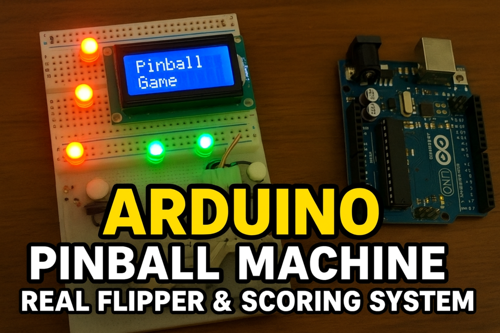
The classic Pinball Game is one of the most popular arcade experiences ever created — combining mechanical action, lights, and quick reflexes into a fun and challenging game. With the rise of DIY electronics and open-source platforms, recreating such arcade-style systems has become possible using Arduino microcontrollers and simple electronic components.
In this project, developed by Arduino Expert, we designed a Pinball Game using Arduino, which replicates the functionality of traditional pinball machines in a modern, microcontroller-based setup. This project demonstrates how embedded systems, servo motors, limit switches, and LED indicators can work together to create an interactive and fun game that also teaches important principles of Arduino programming, sensor interfacing, and real-time control systems.
This project is a perfect blend of fun and learning, showcasing how product design and development can merge gaming concepts with automation and electronics.
Pinball Game Project Overview
The Arduino Pinball Game consists of an Arduino Mega board that controls all the inputs and outputs — including the flipper mechanisms, LED targets, limit switches, and an LCD display for score tracking. Players operate the flippers using two push buttons, which activate servo motors that mimic the motion of mechanical flippers found in real pinball machines.
When the ball (or metallic object) hits certain points on the playfield, limit switches detect contact and reward the player with points. Each hit is displayed on a 16×2 I2C LCD, keeping score in real-time.
This system uses multiple LEDs as visual indicators that light up whenever specific switches are triggered, adding to the excitement and visual feedback of the game.
Working Principle of Pinball Game
The working of this project can be divided into three main parts:
1. Flipper Control
Two servo motors act as the left and right flippers. They are controlled by two push buttons connected to the Arduino.
- When the left button is pressed, the left servo rotates forward, hitting the ball.
- When the right button is pressed, the right servo activates similarly.
After each press, the servo returns to its default position, simulating flipper movement.
2. Score Detection and Display
Each scoring target or point on the playfield is equipped with a limit switch (or microswitch). When the ball contacts these points:
- The Arduino detects the HIGH signal from the switch.
- It increments the player’s score.
- The LCD display updates to show the new total points.
- Corresponding LED indicators flash briefly to visually confirm the hit.
This provides instant feedback to the player — both visually and on the display — just like a real arcade pinball machine.
3. Lighting and Effects
Multiple LEDs positioned around the playfield act as indicators or scoring lights.
Each LED corresponds to different switches, making the gameplay interactive and visually dynamic.
This feature also teaches about digital output control, an essential part of Arduino-based systems.
Components Used in Pinball Game
- Arduino Mega
- 16×2 I2C LCD Display
- Servo Motors (x2) for flippers
- Push Buttons (x2) for user input
- Power Control Button
- Limit Switches (x3 or more) for detecting ball hits
- LEDs (x7) or Even More for scoring indicators
- Resistors, Jumper Wires, and Breadboard
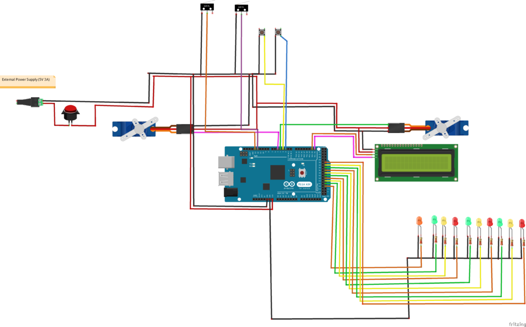
Circuit Diagram of Pin Ball Game with Arduino Mega
Arduino Code for Pin Ball Game
#include <Wire.h>                           // including Wire Library
#include <LiquidCrystal_I2C.h>                  // including LCD Library
LiquidCrystal_I2C lcd(0x27, 16, 2);

#include <Servo.h>


int led_midle = 31 ;
int led_Left_f1 = 33 ;
int led_right_f2 = 35;
int led_f3 = 37;
int led_f4 = 39;
int led_f5 = 41;
int led_f6 = 43;
int led_f7 = 45;

int button_left = 2 ;
int button_right = 3 ;

int limit_midle = 55;
int limit_left = 13;
int limit_right = 12;

Servo  servo_left;
Servo  servo_right;


int points;

int limit_left_State = 0;
int last_limit_left_State = 0;
int limit_right_State = 0;
int last_limit_right_State = 0;
int limit_midle_State = 0;
int last_limit_midle_State = 0;


void setup()

{ // Data Transmission Function

  Serial.begin(9600);                  // Starting Serial Communication
  lcd.begin();                    // Starting LCD
  servo_left.attach(9);
  servo_right.attach(9);

  pinMode (led_midle, OUTPUT);
  pinMode (led_Left_f1, OUTPUT);
  pinMode (led_right_f2, OUTPUT);
  pinMode (led_f3, OUTPUT);
  pinMode (led_f4, OUTPUT);
  pinMode (led_f5, OUTPUT);
  pinMode (led_f6, OUTPUT);
  pinMode (led_f7, OUTPUT);

  pinMode (button_left, INPUT_PULLUP);
  pinMode (button_right, INPUT_PULLUP);
  pinMode (limit_left, INPUT);
  pinMode (limit_right, INPUT);
  pinMode (limit_midle, INPUT);
  lcd.setCursor(0, 0);
  lcd.clear();
  lcd.print("  Pinball Game " );
  delay(1000);
}


void loop()

{

  limit_right_State = digitalRead(limit_right);
  limit_left_State = digitalRead(limit_left);
  limit_midle_State = digitalRead(limit_left);


  if ( digitalRead(button_left == HIGH ))
{

  servo_left.write(90);
    delay(1000);
    servo_left.write(0);
  }

  if ( digitalRead(button_right == HIGH ))
{

  servo_right.write(90);
    delay(1000);
    servo_right.write(0);
  }

  if ( limit_left_State == HIGH && last_limit_left_State == LOW) {

  points += 10;
  lcd.clear();
    lcd.setCursor(0, 0);
    lcd.print(" Points= " );
    lcd.print(points);
    digitalWrite (led_Left_f1 , HIGH);
    digitalWrite (led_right_f2 , LOW);
    digitalWrite (led_midle , LOW);
    digitalWrite (led_f3 , LOW);
    digitalWrite (led_f4, LOW);
    digitalWrite (led_f5 , LOW);
    digitalWrite (led_f6 , LOW);
    digitalWrite (led_f7 , LOW);

  }

  if ( limit_right_State == HIGH && last_limit_right_State == LOW) {

  points += 10;
  lcd.clear();
    lcd.setCursor(0, 0);
    lcd.print(" Points= " );
    lcd.print(points);
    digitalWrite (led_Left_f1 , LOW);
    digitalWrite (led_right_f2 , HIGH);
    digitalWrite (led_midle , LOW);
    digitalWrite (led_f3 , LOW);
    digitalWrite (led_f4, LOW);
    digitalWrite (led_f5 , LOW);
    digitalWrite (led_f6 , LOW);
    digitalWrite (led_f7 , LOW);

  }
  if ( limit_midle_State == HIGH && last_limit_midle_State == LOW) {

  points += 10;
  lcd.clear();
    lcd.setCursor(0, 0);
    lcd.print(" Points= " );
    lcd.print(points);
    digitalWrite (led_Left_f1 , LOW);
    digitalWrite (led_right_f2 , LOW);
    digitalWrite (led_midle , HIGH);
    digitalWrite (led_f3 , LOW);
    digitalWrite (led_f4, LOW);
    digitalWrite (led_f5 , LOW);
    digitalWrite (led_f6 , LOW);
    digitalWrite (led_f7 , LOW);

  }

  last_limit_left_State = limit_left_State;
  last_limit_right_State = limit_right_State;
  last_limit_midle_State = limit_midle_State;
}
Arduino Pinball Game Logic Control
The Arduino program initializes all input/output pins and sets up the LCD display.
In the main loop:
- It continuously reads the button inputs and limit switch states.
- When a button is pressed, the corresponding servo motor activates.
- When a switch is hit, the score increases, and LEDs flash.
- The LCD continuously updates to show the live score.
Serial communication is also enabled for debugging or monitoring data through the Arduino IDE’s serial monitor.
Applications of Arduino Pinball Game
- STEM Education Projects: Demonstrates the integration of mechanics, electronics, and programming.
- DIY Arcade Games: Ideal for creating small, interactive entertainment setups.
- Learning Platform: Helps beginners understand servo control, sensor interfacing, and real-time event handling.
- Product Development and Prototyping: The concept can be extended to build larger gaming or mechanical automation systems.
Conclusion
The Arduino Pinball Project is an engaging way to explore mechatronic control, interactive electronics, and real-time Arduino programming. It’s a compact yet powerful example of how product design and development can merge traditional entertainment concepts with modern embedded technology.
Through this project, users not only build a fun and responsive game but also gain hands-on experience in hardware control, scoring logic, and automation — valuable skills for both students and engineers interested in embedded systems.
Need Help in Arduino Pinball Game Project?
If you need Arduino Pinball Game Project with or without Modifications or Customization then you can contact us through WhatsApp/Email.
Learn More about the services we offer.