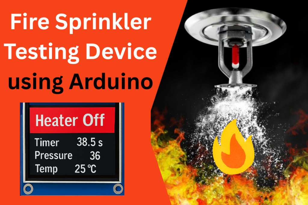
In the domain of fire safety, testing sprinkler systems under realistic and controlled conditions is essential to ensure their effectiveness and compliance with safety standards. Manual or outdated test setups often lack precision, automation, and fail to simulate critical emergency scenarios accurately. To address this, we present a modern, Arduino-based Fire Sprinkler Test Device designed to simulate fire conditions in a precise, automated, and repeatable way.
This device uses a PID controller implemented on an Arduino Mega to regulate a heating element, mimicking the temperature conditions that might activate a real sprinkler. It integrates high-accuracy sensors, including a K-type thermocouple with MAX6675 and an industrial pressure transducer, for real-time temperature and pressure monitoring. A 2.4″ TFT LCD touchscreen or Nextion Touch Display enables the operator to interact with the device through a modern graphical interface.
Advanced logic within the device automatically detects critical activation conditions—such as a sudden drop in temperature or a rapid pressure increase—and triggers the sprinkler logic accordingly. The system provides live monitoring, timing functions, and visual alerts, making it an ideal platform for fire safety testing, educational demonstrations, and product development.
Working Principle of the Arduino Fire Sprinkler Testing Device:
The Fire Sprinkler Test Device is designed to simulate real-life fire conditions in a controlled environment to test the activation behavior of sprinkler systems. Its working is based on real-time sensing, intelligent logic, and PID-based heating control.
Components Used in Fire Sprinkler Testing Device:
| Component | Description |
|---|---|
| Arduino Mega / Uno | Main controller. Mega is preferred for more I/O pins and better memory. |
| K-Type Thermocouple + MAX6675 | High-temperature sensing; MAX6675 interfaces via SPI. |
| Simple Mechanical or Solid State Relay (SSR) | Switches the heating element ON/OFF based on PID output. |
| 4–20mA Pressure Transducer | Measures water line pressure in real-time; mapped to kPa or PSI. |
| 2.4” TFT LCD Touchscreen or Nextion Touch LCD | Used for control, real-time data display, and visual alerts. |
| Heatsink | Ensures safe thermal management around heating components and SSR. |
| Touch Interface | Enables test initiation without external buttons. |
Features of Fire Sprinkler Testing Device:
1. PID-Controlled Heating System
- A PID algorithm controls the heating element to linearly ramp up the temperature over time.
- Using
PID_v1library, the system adjusts heating intensity to achieve:- Smooth, stable increases in temperature.
- Minimal overshoot.
- The heating rate can be adjusted (e.g., 0.1°C/second), and time-proportional control is used via SSR.
2. Real-Time Sensor Monitoring
- Temperature:
- Read from a K-type thermocouple through the MAX6675 module.
- Displayed in real time in °C.
- Pressure:
- Measured using a 4–20mA industrial pressure transducer connected to an analog input.
- Mapped accurately to show values in kPa or PSI.
- Both values are constantly updated on the screen and are also accessible via the Serial Monitor for debugging or logging.
3. Sprinkler Activation Detection Logic
The device automatically checks for two critical conditions:
- Sudden temperature drop (≥10°C) — may indicate sprinkler release (cold water contact).
- Pressure spike (≥100 kPa) — could suggest rapid hydraulic activation.
These conditions are monitored within a rolling 5-second window. If either condition is followed by the other within this time:
- Heater is immediately turned off.
- A “Sprinkler Activated” alert is triggered visually on the screen.
4. Interactive Touch-Based User Interface
- A START button appears on the touchscreen when the device powers on.
- Once tapped:
- Test starts.
- Heater begins ramping temperature.
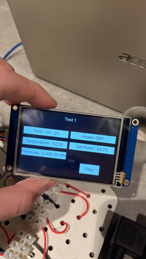
- Screen displays:
- “Test Running”
- “Heater On”
- Elapsed time (MM:SS)
- Current pressure and temperature
- If sprinkler is activated, display shows:
- Red Banner: “Sprinkler Activated”
- Yellow Box: “Heater Off”
5. Real-Time Timer Function
- The timer tracks how long the test has been running.
- Displayed in minutes:seconds format.
- Used to:
- Dynamically calculate temperature setpoints.
- Synchronize detection logic for sprinkler activation.
Working of Fire Sprinkler Testing Device:
Step 1: Power-On
- Arduino initializes the screen, sensors, and PID parameters.
- Displays a START button on the touchscreen.
Step 2: Start Test
- When the user taps START:
- PID controller begins heating.
- Heater is turned ON via SSR.
- Real-time pressure and temperature data begin displaying on screen.
Step 3: Monitoring and Control
- Temperature increases linearly as per defined heating rate.
- Device reads temperature and pressure every few hundred milliseconds.
- PID output adjusts heater duty cycle.
Step 4: Sprinkler Activation (if triggered)
- If both conditions (pressure spike and temperature drop) are detected within a 5-second span:
- Heater is immediately turned off.
- Alerts are shown on screen.
- System enters alert state (can be reset manually or via power cycle).
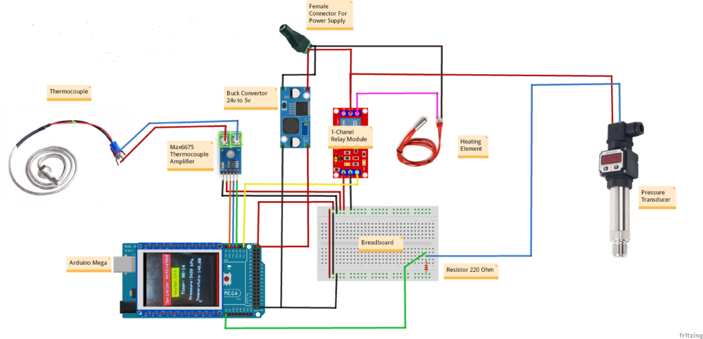
Circuit Diagram of Fire Sprinkler Testing Device with Arduino:
Arduino Code for Fire Sprinkler Testing Device:
#include <Adafruit_GFX.h>
#include <MCUFRIEND_kbv.h>
MCUFRIEND_kbv tft;
#include <TouchScreen.h>
#include "max6675.h"
#include <PID_v1.h>

//----------------------------Thermocouple Declaration-----------------------------
int Temp_Threshold = 10;
int thermoDO = 19;  //SO
int thermoCS = 18;  //CS
int thermoCLK = 17; // SCK
MAX6675 thermocouple(thermoCLK, thermoCS, thermoDO);
const int Relay_pin = 21;
int previousTime;
double setPoint, outputVal;
int TEMP_READ_DELAY = 500;
double temperature = 0, last_temperature, last_temperature2;
unsigned long lastTempUpdate; //tracks clock time of last temp update

//----------------------------PID Parameters--------------------------

//------------------------------------------
int Experiment_Time = 12;   // In minutes
int Reading_Time = 5;       //In Seconds
int Current_Temperature = 30; // You can mention the room temperature here to speed up the test
float Heating_Rate = 0.1, s;    // Heating Rate is 1 degree pe 4 seconds or 0.25 degree per second
//-----------------------------------------


double Setpoint, Input, Output;
double Kp = 200, Ki = 5, Kd = 1;
PID myPID(&Input, &Output, &Setpoint, Kp, Ki, Kd, DIRECT);
double seconds;
int WindowSize = 2000;
unsigned long windowStartTime;
unsigned long lastPrint;
int last_Seconds, Seconds, i = 0, S;

//----------------------------Pressure Sensor Declaration--------------------------
#define Pressure_SENSOR_PIN  A8 //Pressure Sensor Pin
float  current, volts;


//----------------------------2.4" TFT LCD Pins Declaration-------------------------
#define MINPRESSURE 10
#define MAXPRESSURE 1000
const int XP = 8, XM = A2, YP = A3, YM = 9;  // 240x320 ID=0x7789
const int TS_LEFT = 69, TS_RT = 959, TS_TOP = 48, TS_BOT = 916;
TouchScreen ts = TouchScreen(XP, YP, XM, YM, 300);
Adafruit_GFX_Button start_btn;
int pixel_x, pixel_y;  // Touch_getXY() updates global vars

#define BLACK 0x0000
#define BLUE 0x001F
#define RED 0xF800
#define GREEN 0x07E0
#define CYAN 0x07FF
#define MAGENTA 0xF81F
#define YELLOW 0xFFE0
#define WHITE 0xFFFF


bool sprinklerActivated = false, start = false, min = true,
     flag1 = true, flagP = false, flagT = false, flagSprinkler = true, Heater = false;
unsigned long startTime = 0, Start_time;
unsigned long elapsedTime = 0;
double pressure = 0, last_pressure, last_pressure2;
unsigned int minutes = 0, last_minutes = 0;
unsigned int  last_seconds = 0;


bool updateTemperature() {
  if ((millis() - lastTempUpdate) > TEMP_READ_DELAY) {
    temperature = thermocouple.readCelsius(); //get temp reading
    lastTempUpdate = millis();
    return true;
  }
  return false;
}


void setup(void) {
  Serial.begin(9600);
  windowStartTime = millis();
  pinMode(Relay_pin, OUTPUT);
  uint16_t ID = tft.readID();
  if (ID == 0xD3D3) ID = 0x9486;  // write-only shield
  tft.begin(ID);
  tft.setRotation(0);  // PORTRAIT
  tft.fillScreen(BLACK);
  digitalWrite(Relay_pin, LOW);  // Turn OFF heater
  Serial.println((String)"\tSystem ON");

  //tell the PID to range between 0 and the full window size
  myPID.SetOutputLimits(0, WindowSize);
  //turn the PID on
  myPID.SetMode(AUTOMATIC);

}
Applications of Fire Sprinkler Testing Device:
| Sector | Application |
|---|---|
| Fire Safety Industry | Simulate and validate sprinkler activation logic in a controlled setting. |
| R&D and QA Labs | Use in development and testing of fire suppression systems. |
| Engineering Education | Teach advanced topics like PID control, sensor interfacing, and embedded safety logic. |
| Experimental Research | Develop and test responses of fire safety equipment under varying conditions. |
Conclusion
The Fire Sprinkler Test Device described here provides a sophisticated and compact solution for simulating fire-related conditions in a lab or industrial setting. Using real-time PID-controlled heating, accurate sensor feedback, and a touchscreen GUI, it replicates the conditions under which a sprinkler would activate—allowing for rigorous, repeatable, and safe testing.
Its intuitive design, affordable components, and smart logic make it suitable for engineers, researchers, educators, and developers alike. This device not only enables accurate testing but also provides a platform for understanding and improving real-world safety systems.
Need This Project?
If you need Fire Sprinkler Testing Device Project with or without Modifications or Customization then you can contact us through WhatsApp. We can deliver you this Project in the Following Ways.
Project Code:
we can provide you Project Code along with Zoom Assistant, through Zoom meeting for Setup of this Project or any other Arduino Project of your need.
Fully Functional Project with Hardware/Components Shipment:
if you can not make this project yourself then you can use this option. We will assemble the Project and will ship it to your Doorstep with Safe Packaging.
Learn More about the services we offer.