Digital scoreboards are widely used in sports events, counters, public displays, and industrial systems where numerical information must be presented clearly. This project demonstrates how to design a Digital Score Display using an Arduino microcontroller and four multiplexed seven-segment displays.
The project utilizes the Arduino Programming Language to control multiple displays with minimal pins through fast multiplexing. The system reads input signals from three push buttons:
- Increment Button → increases the score
- Decrement Button → decreases the score
- Reset Button → resets the score to zero
This project is a strong example of Product Design and Development because it uses real-world techniques like display multiplexing, hardware debouncing, optimized pin usage, and human-machine interaction principles.
The seven-segment display is divided into:
- Four digit selectors (D1, D2, D3, D4)
- Eight segment pins (A–G and DP)
Your code dynamically updates each digit thousands of times per second, creating a seamless and stable display output. The score value is split into thousands, hundreds, tens, and units, and displayed across the four digits.
This design demonstrates the principles of Smart Device prototyping, embedded systems, and digital display engineering, making it ideal for academic projects, competitions, and real-world scoreboard applications.

Digital Score Display Project Functionality
The Digital Score Display with Arduino and Seven-Segment Displays is a four-digit scoreboard system that allows the user to increase, decrease, and reset the score using push buttons. The Arduino reads the button inputs and updates the score in real time.
The system uses multiplexing to drive four seven-segment displays with minimal pins. The score is split into thousands, hundreds, tens, and units and displayed across the four digits. Segment patterns are controlled through the Arduino to show numbers 0–9.
The display supports both common-cathode and common-anode configurations, making it versatile for different seven-segment modules. The system includes debouncing to ensure clean button input. A reset function clears the display and score back to zero.
In summary, the project provides a simple, efficient digital score counter with real-time display, button control, and stable multiplexed seven-segment output.
Features of Digital Score Display System
→Real-Time 4-Digit Score Display
Clear and stable output using multiplexed seven-segment displays.
→User Button Control
Increment, decrement, and reset—the core functions of any scoreboard.
→Optimized Pin Usage
Multiplexing allows 4 digits using only 12 pins.
→Versatile Design
Compatible with both common-cathode and common-anode displays.
→Beginner-Friendly Arduino Programming
Uses fundamental concepts like pin control, loops, condition checks, and arrays.
→Ideal for Product Design and Development
A practical example of how digital scoreboards and counters work.
→Expandable Smart Device Foundation
Can be upgraded with wireless control, Bluetooth, or IoT features.
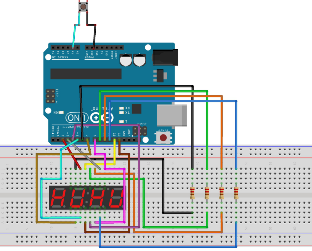
Circuit Diagram of Electronic Score Display with Arduino
Arduino Code for Digital Scoring System
#define common_cathode 0
#define common_anode 1
#define pinA 2
#define pinB 3
#define pinC 4
#define pinD 5
#define pinE 7
#define pinF 12
#define pinG 8
#define pinDP 13
#define D1 6
#define D2 9
#define D3 10
#define D4 11
#define DP 30
#define Btn A1

String Nmbr="1234";
bool Type = common_anode;// Selet the display type

const int charsInArray = 37;
byte digits[]{D1,D2,D3,D4}; // defining the digit pins
byte seg[] {pinA,pinB,pinC,pinD,pinE,pinF,pinG,pinDP}; // defining the seven segment pins
byte Char[37][9] {

            {1,1,1,1,1,1,0,0,'0'},//0
            {0,1,1,0,0,0,0,0,'1'},//1
            {1,1,0,1,1,0,1,0,'2'},//2
            {1,1,1,1,0,0,1,0,'3'},//3
            {0,1,1,0,0,1,1,0,'4'},//4
            {1,0,1,1,0,1,1,0,'5'},//5
            {1,0,1,1,1,1,1,0,'6'},//6
            {1,1,1,0,0,0,0,0,'7'},//7
            {1,1,1,1,1,1,1,0,'8'},//8
            {1,1,1,1,0,1,1,0,'9'}, //9
            {1,1,1,0,1,1,1,0,'a'},//A/1
            {0,0,1,1,1,1,1,0,'b'},//b/2
            {0,0,0,1,1,0,1,0,'c'},//C/3
            {0,1,1,1,1,0,1,0,'d'},//d/4
            {1,0,0,1,1,1,1,0,'e'},//E/5
            {1,0,0,0,1,1,1,0,'f'},//F/6
            {1,0,1,1,1,1,0,0,'g'},//G/7
            {0,1,1,0,1,1,1,0,'h'},//H/8
            {0,1,1,0,0,0,0,0,'i'},//I/9
            {0,1,1,1,1,0,0,0,'j'},//J/10
            {0,0,0,1,1,1,0,0,'l'},//L/11
            {0,0,1,0,1,0,1,0,'n'},//n/12
            {0,0,1,1,1,0,1,0,'o'},//o/13
            {1,1,0,0,1,1,1,0,'p'},//P/14
            {1,1,1,0,0,1,1,0,'q'},//q/15
            {0,0,0,0,1,0,1,0,'r'},//r/16
            {1,0,1,1,0,1,1,0,'s'},//S/17
            {0,0,0,1,1,1,1,0,'t'},//t/18
            {0,1,1,1,1,1,0,0,'u'},//U/19
            {0,1,1,1,0,1,1,0,'y'},//y/20
            {0,0,0,0,0,0,0,1,'.'},//.
            {0,0,0,0,0,0,1,0,'-'},//dash/negative
            {0,0,0,1,0,0,0,0,'_'},//underscore
            {1,0,0,1,1,1,0,0,'['},//[
            {1,1,1,1,0,0,0,0,']'},//]
            {1,1,0,0,1,0,1,0,'?'},//?
            {0,0,0,0,0,0,0,0,' '}//blank

            };


void setup() {
  // initialize the I/O pins
  pinMode(pinA, OUTPUT);
  pinMode(pinB, OUTPUT);
  pinMode(pinC, OUTPUT);
  pinMode(pinD, OUTPUT);
  pinMode(pinE, OUTPUT);
  pinMode(pinF, OUTPUT);
  pinMode(pinG, OUTPUT);
  pinMode(pinDP, OUTPUT);
  pinMode(D1, OUTPUT);
  pinMode(D2, OUTPUT);
  pinMode(D3, OUTPUT);
  pinMode(D4, OUTPUT);
  pinMode(Btn, INPUT_PULLUP);
  Serial.begin(9600); // Initialize the serial communication.
  Serial.println(" ");
}


void loop() {

print_number(Nmbr); //Print the number of seven segment display
Reset_Seven_Segment();// Reset the seven segment
}


void print_number(String text)
{
char char1 = text.charAt(0);
char char2 = text.charAt(1);
char char3 = text.charAt(2);
char char4 = text.charAt(3);

int nmbr_of_digits = text.length();

if(nmbr_of_digits < 6){

  while(digitalRead(Btn)==HIGH){

    if (Serial.available()>0)
    {
      Reset_Seven_Segment();
      Nmbr=Serial.readString();
      Serial.println((String)"Number Received "+Nmbr);
      }
  if(1 > nmbr_of_digits) char1 = ' ';
  else char1 = text.charAt(0);
  if(2 > nmbr_of_digits) char2 = ' ';
  else char2 = text.charAt(1);
  if(3 > nmbr_of_digits) char3 = ' ';
  else char3 = text.charAt(2);
  if(4 > nmbr_of_digits) char4 = ' ';
  else char4 = text.charAt(3);
  print_char(char1,D1);
  delay(2);
  print_char(char2,D2);
  delay(2);
  print_char(char3,D3);
  delay(2);
  print_char(char4,D4);
  delay(2);
  }
  Serial.println("Button Pressed");

}
}


void print_char(char ch,int digit_number)
{ Reset_Seven_Segment();
  int character = -1;
  digitalWrite(digit_number,Type);
  for(int i = 0 ; i < charsInArray ; i++){

    if(ch == Char[i][8]){
      character = i;
    }
  }
  if (character == -1){
    digitalWrite(pinG,!Type);
  }else{
for(int i = 0;i<= 7;i++)
    {if(Type == common_anode) digitalWrite(seg[i],!Char[character][i]);
    else if(Type == common_cathode) digitalWrite(seg[i],Char[character][i]);

    }
  }
}

void Reset_Seven_Segment()
{ digitalWrite(D1, !Type);
  digitalWrite(D2, !Type);
  digitalWrite(D3, !Type);
  digitalWrite(D4, !Type);
  for(byte i = 0 ; i < 8 ; i++){
  digitalWrite(seg[i],Type);
  }
}
Applications of the Score Indicator Display Project
→Sports Scoreboard
Basketball, football, cricket, table tennis, badminton, etc.
→Digital Counter for Laboratories
Count samples, events, repetitions.
→Industrial Counters
Counting items on conveyor belts or production lines.
→Educational Demonstration
Used to teach:
- Multiplexing
- Seven-segment control
- Arduino programming
- Digital electronics
→Game Score Display
Arcade games, competitions, quiz buzzers.
→Retail Display Units
Customer counters, queue numbers, token displays.
Conclusion
The Digital Score Display with Arduino and Seven-Segment Display is a powerful yet simple Smart Device that demonstrates the core principles of embedded system design, user interface development, and digital electronics. With a clear four-digit output and intuitive button control, it is ideal for sports applications, industrial counters, educational tools, and interactive products. By using the Arduino Programming Language and efficient multiplexing techniques, this project is a professional example of Product Design and Development in the world of modern digital displays.
Need Help/Assistance in Digital Score Display System Project?
If you need any help or assistance in Digital Score Counter Display Project with or without Modifications/Customization then you can contact us through WhatsApp.
Learn More about the services we offer