In today’s era of Smart Devices and Automation, wireless control systems are becoming an essential part of modern Product Design and Development. Bluetooth-based control systems are widely used because of their low cost, ease of implementation, and high reliability for short-range communication.
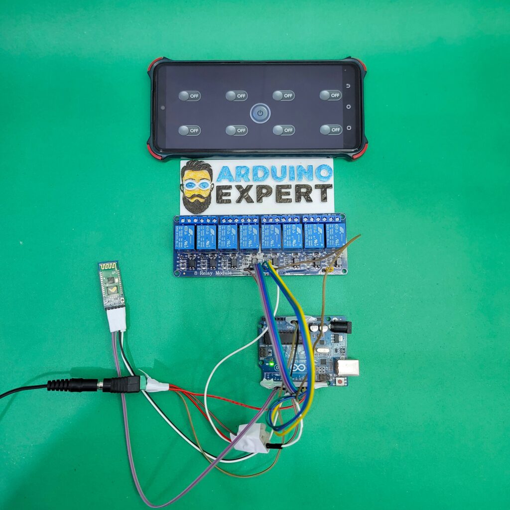
In this project, “8-Channel Relay Control LED Lights with Arduino and Bluetooth App”, we design and develop a smart relay automation system using Arduino UNO, HC-05 Bluetooth module, and a 5V 8-channel relay module. The system allows users to wirelessly control up to eight LED lights using an Android smartphone through the Bluetooth Electronics App.
This project is ideal for beginners and professionals who want hands-on experience with:
- Arduino Programming Language
- Bluetooth-based Smart Device Control
- Relay interfacing
- Home and industrial automation prototypes

If you want to control Relay with Wi-Fi over the internet then you can check our this Project.
Objective of 8 Channel Relay Control Project
The main objective of this project is to design a Bluetooth-controlled smart switching system that can:
- Control 8 individual LED lights using a mobile app
- Turn all lights ON or OFF with a single button
- Demonstrate real-world use of Arduino-based relay automation
- Provide a scalable foundation for home automation and product development projects
Working Principle of the 8 Channel Relay Control Project
The system works on Bluetooth serial communication between the HC-05 module and the Arduino UNO.
Step-by-Step Operation:
- The user presses a button in the Bluetooth Electronics App
- The app sends a single character command via Bluetooth
- The HC-05 module receives this command and passes it to Arduino using SoftwareSerial
- The Arduino UNO processes the command using the Arduino programming language
- Based on the command:
- A specific relay turns ON or OFF
- Or all relays are activated together
- The relay controls the LED lights connected to its output terminals
This makes the entire system a wireless smart device with instant response.
Components Used in 8 Channel Relay Control Project
| Component | Description |
|---|---|
| Arduino UNO | Main microcontroller for logic and control |
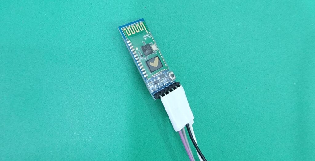
| HC-05 Bluetooth Module | Wireless communication interface |
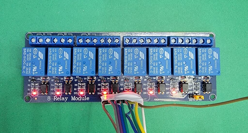
| 5V 8-Channel Relay Module | Controls LED lights electrically |
| LED Lights | Load devices for demonstration |
| 5V External Power Supply | Dedicated power for relay module |
| Jumper Wires | Circuit connections |
| Android Smartphone | Runs Bluetooth Electronics App |
Why External 5V Power Supply Is Used?
The 8-channel relay module requires higher current than the Arduino UNO can safely provide. Therefore:
- A 5V external power supply is used for relays
- Arduino GND is common with relay GND
- This improves system stability, safety, and reliability
- It is a best practice in professional product design and development
Circuit Diagram of 8 Channel Relay and HC-05 with Arduino

HC-05 Bluetooth Module (SoftwareSerial)
- HC-05 TX → Arduino Pin 3
- HC-05 RX → Arduino Pin 4 (with voltage divider recommended)
- Baud Rate: 9600
Relay Connections
| Relay | Arduino Pin |
|---|---|
| Relay 1 | 5 |
| Relay 2 | 6 |
| Relay 3 | 7 |
| Relay 4 | 8 |
| Relay 5 | 9 |
| Relay 6 | 10 |
| Relay 7 | 11 |
| Relay 8 | 12 |
Arduino Code for Bluetooth-Based 8 Channel Relay Control System
/***************************************************
   Arduino UNO + HC-05 (SoftwareSerial)
   8 Relay Control + ALL ON / ALL OFF
****************************************************/

#include <SoftwareSerial.h>

// HC-05 SoftwareSerial
SoftwareSerial BT(3, 4);   // RX, TX

// Relay Pins
#define R1  5
#define R2  6
#define R3  7
#define R4  8
#define R5  9
#define R6  10
#define R7  11
#define R8  12

void allRelaysOn() {
  digitalWrite(R1, LOW);
  digitalWrite(R2, LOW);
  digitalWrite(R3, LOW);
  digitalWrite(R4, LOW);
  digitalWrite(R5, LOW);
  digitalWrite(R6, LOW);
  digitalWrite(R7, LOW);
  digitalWrite(R8, LOW);
}

void allRelaysOff() {
  digitalWrite(R1, HIGH);
  digitalWrite(R2, HIGH);
  digitalWrite(R3, HIGH);
  digitalWrite(R4, HIGH);
  digitalWrite(R5, HIGH);
  digitalWrite(R6, HIGH);
  digitalWrite(R7, HIGH);
  digitalWrite(R8, HIGH);
}

void setup() {
  Serial.begin(9600);
  BT.begin(9600);

  pinMode(R1, OUTPUT);
  pinMode(R2, OUTPUT);
  pinMode(R3, OUTPUT);
  pinMode(R4, OUTPUT);
  pinMode(R5, OUTPUT);
  pinMode(R6, OUTPUT);
  pinMode(R7, OUTPUT);
  pinMode(R8, OUTPUT);

  // Start with all relays OFF
  allRelaysOff();

  Serial.println("Bluetooth Relay Control Ready");
}

void loop() {

  if (BT.available()) {
    char cmd = BT.read();
    Serial.println(cmd);

    switch (cmd) {

      case 'A': digitalWrite(R1, LOW);  break;
      case 'a': digitalWrite(R1, HIGH); break;

      case 'B': digitalWrite(R2, LOW);  break;
      case 'b': digitalWrite(R2, HIGH); break;

      case 'C': digitalWrite(R3, LOW);  break;
      case 'c': digitalWrite(R3, HIGH); break;

      case 'D': digitalWrite(R4, LOW);  break;
      case 'd': digitalWrite(R4, HIGH); break;

      case 'E': digitalWrite(R5, LOW);  break;
      case 'e': digitalWrite(R5, HIGH); break;

      case 'F': digitalWrite(R6, LOW);  break;
      case 'f': digitalWrite(R6, HIGH); break;

      case 'G': digitalWrite(R7, LOW);  break;
      case 'g': digitalWrite(R7, HIGH); break;

      case 'H': digitalWrite(R8, LOW);  break;
      case 'h': digitalWrite(R8, HIGH); break;

      //  NEW COMMANDS
      case 'Z': allRelaysOn();  break;   // ALL ON
      case 'z': allRelaysOff(); break;   // ALL OFF (recommended)
    }
  }
}
Relay Logic Used in This Project
The 5V relay module is active-LOW, meaning:
- LOW → Relay ON
- HIGH → Relay OFF
This logic is carefully implemented in the code to ensure:
- Safe startup (all relays OFF)
- Reliable switching
- Compatibility with commercial relay boards
Project Code Functionality
The Arduino code listens continuously for Bluetooth commands and performs the following actions:
→Individual Relay Control
Each relay is controlled using unique character commands:
| Relay | ON Command | OFF Command |
|---|---|---|
| Relay 1 | A | a |
| Relay 2 | B | b |
| Relay 3 | C | c |
| Relay 4 | D | d |
| Relay 5 | E | e |
| Relay 6 | F | f |
| Relay 7 | G | g |
| Relay 8 | H | h |
When the Arduino receives these commands, it changes the output pin state accordingly, switching the LED lights ON or OFF.
→All Relays Control (Smart Feature)
An additional smart automation feature is implemented:
| Function | Command |
|---|---|
| ALL Relays ON | Z |
| ALL Relays OFF | z |
This feature is extremely useful in:
- Emergency lighting systems
- Smart home master switch
- Industrial control panels
It demonstrates how smart device logic can be added using simple Arduino programming techniques.
Bluetooth Electronics App Interface
The Bluetooth Electronics App allows users to:
- Create custom buttons
- Assign characters to each button
- Design a professional control panel without coding
Each button in the app corresponds to a relay function, making the system user-friendly and scalable.

Working Video of the Smart Relay Automation Project
Applications of the Smart Relay Automation Project
This project can be used or extended for:
- Smart Home Lighting Control
- Wireless Switch Boards
- Industrial Relay Automation
- Educational Arduino Projects
- Product Prototyping
- IoT and Smart Device Development
- Office and Lab Equipment Control
Conclusion
The 8-Channel Relay Control LED Lights Using Arduino and Bluetooth App project is a powerful demonstration of how Arduino programming language, Bluetooth communication, and relay control can be combined to build a reliable smart device.
By using:
- Arduino UNO
- HC-05 Bluetooth module
- 5V 8-channel relay
- External power supply
we achieve a safe, scalable, and professional automation system suitable for both learning and real-world applications.
This project is an excellent foundation for advanced smart home systems, industrial automation, and custom product development solutions.
Need Help/Assistance in Arduino Bluetooth Relay Control System?
If you need any help or assistance in Arduino Bluetooth Relay Control Project with or without Modifications/Customization then you can contact us through WhatsApp.
Learn More about the services we offer