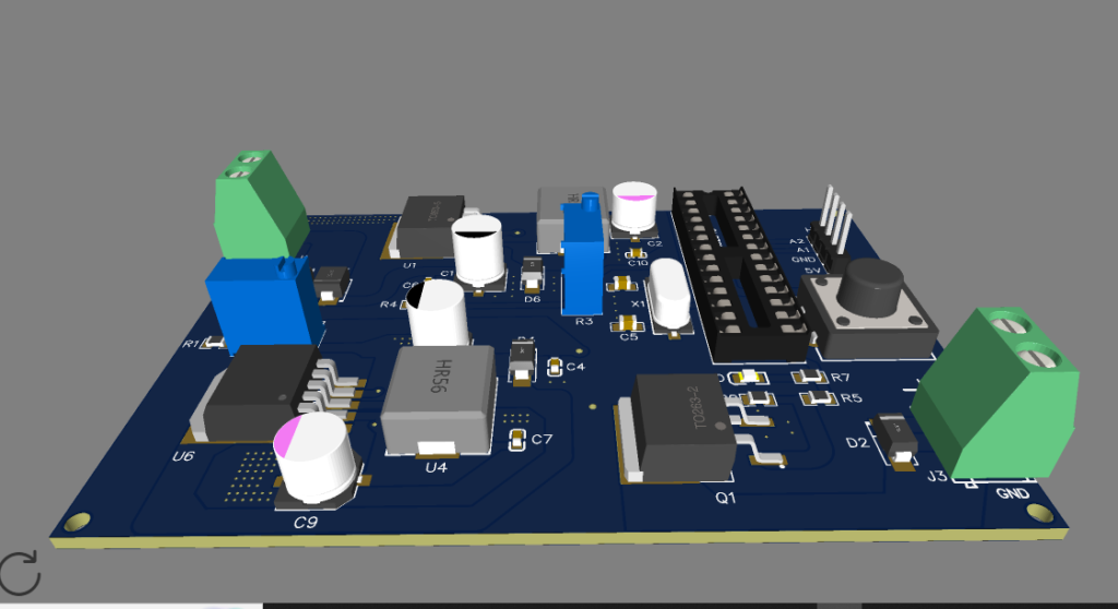
This project focuses on designing a custom modular PCB for a UHF RFID-based door lock security system, built around the ATmega328P Microcontroller, which is the core of the Arduino Uno. The system is engineered to provide a secure, standalone access control solution by integrating UHF RFID technology, a reliable power management system, and electromagnetic lock control.
All components are connected through JST and terminal headers, promoting flexibility and easy maintenance. The design aims for a balance of compactness, expandability, and energy efficiency.

Features of UHF RFID Security System PCB Design Project:
- UHF RFID Access Control
- Electromagnetic Lock Triggering
- Modular Header Connections
- LED Status Indicators
- Efficient Power Regulation and Protection
- Standalone Operation or Expansion via UART/I2C Headers
Components used in UHF RFID Security System PCB Design:
Microcontroller Unit
- ATmega328P (via IC Seat):
Acts as the brain of the system, processing RFID signals and controlling access. The IC is mounted via a socket for ease of replacement and development. - 16MHz Crystal Oscillator
Provides accurate clock signal for the microcontroller. - 22pF Capacitors
Used alongside the crystal oscillator for stable oscillation.
UHF RFID Interface
- UHF RFID Reader (connected via Header-Male-2.54_1x4):
External RFID module reads RFID tags/cards and sends UID to ATmega328P for access verification.
Power Supply & Voltage Regulation
To ensure safe and efficient voltage conversion for various modules, the board integrates both buck and boost converters:
- LM2596S-ADJRG (Buck Converter):
Steps down input voltage (typically 12V) to 5V for powering the microcontroller and logic-level components. - XL6009_C2961880 (Boost Converter):
Steps up voltage when required, for devices needing higher voltage like certain electromagnetic locks. - Schottky Diode (SS34_C908680) and Bridge Rectifier (US3MB):
Provide polarity protection and convert AC input (if used) to DC. - Filtering & Decoupling Capacitors:
- 220µF, 100µF 25V – Bulk filtering for voltage regulators
- 100nF – Noise suppression and decoupling near ICs
- 47µH Inductor – Supports switching regulators for voltage smoothing
Door Lock Control Output
- IRF540NSTRLPBF (N-Channel MOSFET):
Used as a high-side switch to control the power to an electromagnetic lock. Triggered by a digital signal from ATmega328P. - CON_TERMINAL_BLOCK_02:
Used for securely connecting the electromagnetic lock, external power, or expansion modules.
User Interface & Status Indicators
- TS-1003-07526 (Tactile Switch):
Can serve as a reset, manual unlock, or configuration input. - TZ-P2-0805GTCS2-0.8T (Tactile LED Switch):
Combines switch with visual feedback, used for system status or mode selection. - RGB LED / Status LEDs:
Provide real-time visual feedback:- Green for access granted
- Red for access denied
- Blue for standby or scan mode
Resistors (1kΩ, 330Ω, 100Ω, etc.) are used for current-limiting.
Connectivity & Expandability
- Header-Male-2.54_1x4:
Used for programming, debugging, or connecting to Bluetooth, keypad, or other I2C/UART peripherals.

PCB Design Considerations for UHF RFID Security System:
All components are connected via JST headers or terminal blocks, making the board fully modular.
The board is designed with clear silk labels, enabling easy assembly and debugging.
IC seat for ATmega328P enables quick replacement or upgrade of the microcontroller.
Compact layout separates power, control, and interface sections for low noise and reliability.
Working of UHF RFID Security System Project:
The system is powered using a DC input, converted using LM2596 and XL6009 modules.
A user presents their UHF RFID card/tag.
The RFID module sends the UID to ATmega328P, which checks for authorization.
If verified:
- The MOSFET (IRF540N) is triggered, activating the electromagnetic lock.
- Status LEDs give visual feedback (access granted/denied).
System returns to standby mode awaiting the next scan.
Working video of UHF RFID Security System
https://www.youtube.com/watch?v=t_gdKXsKork&t=38s
Applications of UHF RFID Security System PCB Design Project:
Home and Office Access Control
Secure Locker Systems
Industrial Entry Points
Gate Automation Projects
Conclusion:
This UHF RFID-based Door Lock Security System PCB provides a compact, secure, and modular solution for embedded access control. It’s designed for reliability, easy integration, and flexibility in hardware connections. Built using widely available components and Arduino-compatible logic, this board is ideal for rapid deployment in custom security projects.
Need This Project?
If you need this Project with or without Modifications or Customization then you can contact us through WhatsApp. We can deliver you this Project in the Following Ways.
Project Code:
we can provide you Project Code along with Zoom Assistant, through Zoom meeting for Setup of this Project or any other Arduino Project of your need.
Fully Functional Project with Hardware/Components Shipment:
if you can not make this project yourself then you can use this option. We will assemble the Project and will ship it to your Doorstep with Safe Packaging.
Learn More about the services we offer.