This project involves designing a custom modular PCB using Multiple RFIDs Modules for a Security System based on the Arduino UNO platform. The system utilizes 4 RFID modules for user authentication, 2 relays for controlling secure access points (like doors or alarms), and an RGB LED for visual feedback. All components are connected through JST headers for secure, compact, and maintenance-friendly wiring.
The modular approach ensures easy plug-and-play connectivity, simplified troubleshooting, and flexibility for installation in various security scenarios such as office entries, lockers, or automated gates.

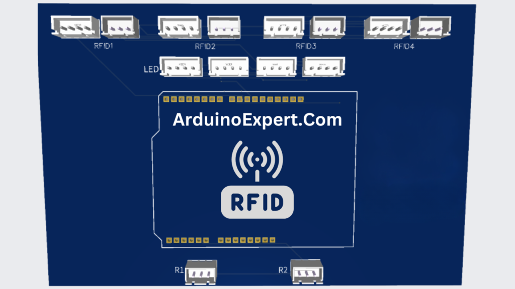
Multiple RFIDs Modules with Arduino PCB Design:
Modular JST Header Design
- Secure and compact: JST connectors ensure tight connections, especially useful in environments prone to vibration or movement.
- Ease of maintenance: Modules can be replaced or tested without soldering.
- Plug-and-play architecture: Simple to deploy in field installations.
Functional PCB Layout
- Organized headers for RFID modules labeled clearly (RFID 1, RFID 2, etc.)
- Relay headers marked with relay number and signal pin.
- RGB LED header pinout labeled (R, G, B, GND).
- Silk screen labels provide quick reference during wiring.
Expandable System
- Though designed for 4 RFIDs and 2 relays, the PCB can be modified for additional inputs and outputs with minimal effort.
Components used in Multiple RFIDs Modules Project:
1. Arduino UNO
- Acts as the brain of the system.
- Processes RFID data, controls relays, and handles LED output.
- Mounted separately and connected to the PCB via headers.
2. Four RFID Modules
- Typically MFRC522 or similar RFID readers.
- Connected via 7-pin JST headers (SPI Interface: SDA, SCK, MOSI, MISO, RST, VCC, GND).
- Each RFID module is assigned to a different zone or access point.
- Positioned externally and interfaced through the JST headers on the PCB.
3. Two Relays
- Controlled via Arduino digital pins.
- Connected via 3-pin JST headers (Signal, VCC, GND).
- Used to activate door locks, alarms, or other security mechanisms based on RFID authentication.
4. RGB LED
- Common cathode or common anode RGB LED for visual system status.
- Connected via a 4-pin JST header (R, G, B, and GND or VCC).
- Used to indicate:
- Green – Access granted
- Red – Access denied
- Blue – System idle or waiting for input
Working of Multiple RFIDs Module Project:
The Arduino UNO software performs the following:
- Initializes and reads data from each RFID reader.
- Matches UID against predefined access list stored in EEPROM or SD card.
- Controls relays for door unlocking upon successful scan.
- Uses the RGB LED to provide visual feedback.
- Logs entries or access attempts (optional).
Conclusion:
This Security System PCB project demonstrates a highly modular and scalable approach to access control. By leveraging JST header connections, the board is easy to assemble, troubleshoot, and upgrade. It’s ideal for smart homes, offices, or shared environments where controlled access is critical. Future iterations may include features like GSM alerts, fingerprint sensors, or real-time logging via the cloud.
Need This Project?
If you need this Project with or without Modifications or Customization then you can contact us through WhatsApp. We can deliver you this Project in the Following Ways.
Project Code:
we can provide you Project Code along with Zoom Assistant, through Zoom meeting for Setup of this Project or any other Arduino Project of your need.
Fully Functional Project with Hardware/Components Shipment:
if you can not make this project yourself then you can use this option. We will assemble the Project and will ship it to your Doorstep with Safe Packaging.
Learn More about the services we offer.