Automation systems that respond intelligently to human presence are becoming increasingly important in industrial machinery, smart infrastructure, security solutions, and custom embedded products. One of the most reliable ways to implement such automation is by combining motion sensing with precision motor control.
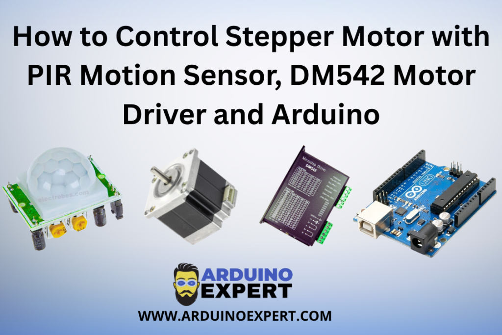
In this project guide, we demonstrate how to control a stepper motor using a PIR motion sensor, Arduino, and DM542 stepper motor driver. The system is designed to automatically activate a high-torque stepper motor when motion is detected, providing accurate, repeatable, and controlled mechanical movement.
Unlike basic DC motor automation, stepper motors allow precise control over rotation, speed, and position, making them ideal for applications where controlled motion is critical. By integrating the DM542 industrial stepper motor driver, this project supports higher current and voltage levels, enabling the use of NEMA 23 stepper motors commonly found in real-world automation systems.
The PIR motion sensor adds an intelligent layer to the system by detecting human movement without physical contact. This enables touch-free activation, improves energy efficiency by running the motor only when needed, and enhances safety in environments where manual switches may not be practical.
The modular architecture of this design allows it to be easily customized for automatic doors, rotating platforms, conveyors, security mechanisms, and exhibition systems. It also serves as a strong reference for developers and companies seeking custom Arduino automation solutions and embedded motor control systems.
Overall, this guide not only explains the technical implementation but also reflects how Arduino Project Services can transform simple sensor input into industrial-grade automation products suitable for real-world deployment.
Project Overview: Stepper Motor Control System
This project demonstrates an automatic stepper motor control system where:
- A PIR motion sensor detects human movement
- An Arduino board processes the motion signal
- A DM542 stepper motor driver drives a high-torque stepper motor
- The stepper motor rotates only when motion is detected
- The system stops or resets when no motion is present
This design is suitable for motion-activated mechanical systems requiring precision and repeatability.
How the System Works
- PIR sensor continuously monitors the surroundings
- When motion is detected:
- PIR output goes HIGH
- Arduino reads the PIR signal
- Arduino sends STEP and DIR pulses to the DM542 driver
- The stepper motor starts rotating
- When motion stops:
- Motor stops after completing the programmed movement
This logic ensures energy efficiency and controlled mechanical movement.
Components Used in Stepper Motor Control System
- Arduino UNO / Nano / Mega
- PIR Motion Sensor (HC-SR501 or equivalent)
- DM542 Stepper Motor Driver
- Stepper Motor (NEMA 23 recommended)
- External DC Power Supply (24V–48V for motor)
- Connecting wires
- Common ground connection
DM542 Stepper Motor Driver Functionality
The DM542 driver acts as an industrial-grade interface between Arduino and the stepper motor.
Why DM542?
- Handles high current and voltage
- Supports microstepping
- STEP/DIR control compatibility with Arduino
- Ideal for NEMA 23 motors
This makes it perfect for Arduino Projects involving automation and motion control.
Learn: How to Control NEMA 23 Stepper Motor with DM542 Driver and Push Buttons Using Arduino
PIR Motion Sensor Functionality
The PIR (Passive Infrared) sensor detects infrared radiation changes caused by human movement.
In this project:
- Output HIGH → Motion detected
- Output LOW → No motion
The PIR sensor acts as a non-contact trigger, enabling touch-free automation.
Check Out Our PIR Sensor Tutorial: How PIR Motion Sensors Work with Arduino
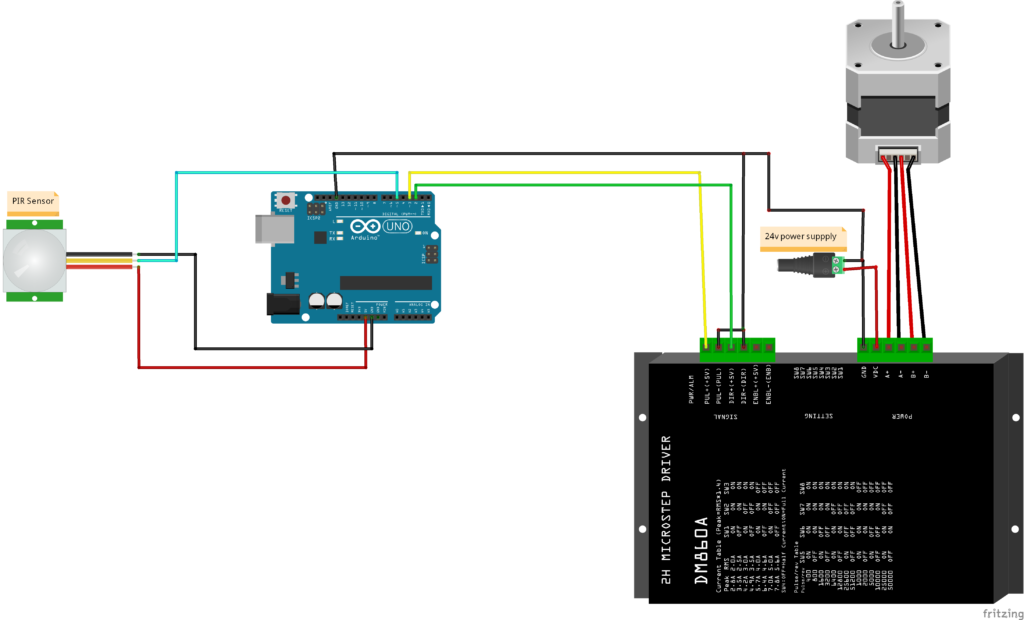
Circuit Diagram of Stepper Motor with PIR Motion Sensor, DM542 Motor Driver and Arduino
Arduino Code for Controlling Stepper Motor with PIR Sensor
const int stepPin = 3;    // Step pin on the DM542 driver
const int dirPin = 2;     // Direction pin on the DM542 driver
float Angle =50; // Here you can right the angle in degrees to move
int steps;
const float MF=1.11;
int PIR=5;

void setup() {
  Serial.begin(9600);
  pinMode(stepPin, OUTPUT);
  pinMode(dirPin, OUTPUT);
  digitalWrite(dirPin, LOW);
  digitalWrite(stepPin, LOW);
  pinMode(PIR,INPUT);
   steps = (MF* Angle);
}

void loop() {

  if(digitalRead(PIR)==HIGH){   // Checking if the sensor triggered
  digitalWrite(dirPin, LOW);  // Setting direction forward
  for(int i = 0; i <steps; i++) {    // Moving forward in 10 seconds
  digitalWrite(stepPin, HIGH);
  delayMicroseconds(1000);
  digitalWrite(stepPin, LOW);
  delayMicroseconds(1000);
  delay(182);
}
delay(20000); // Waiting for 20 seconds

digitalWrite(dirPin, HIGH);   // Setting direction backward
for(int i = 0; i <steps; i++) {   // Moving backward in 10 seconds
  digitalWrite(stepPin, HIGH);
  delayMicroseconds(1000);
  digitalWrite(stepPin, LOW);
  delayMicroseconds(1000);
  delay(182);
}

while(digitalRead(PIR)==HIGH){}

}

}
Arduino Code Functionality
The uploaded Arduino sketch implements motion-based stepper motor control logic.
1. Pin Initialization
- PIR sensor pin configured as INPUT
- STEP and DIR pins configured as OUTPUT
- Motor driver enable logic set during startup
This prepares Arduino for real-time motion control.
2. Motion Detection Logic
- Arduino continuously reads PIR sensor output
- When PIR output is HIGH:
- Motion is detected
- When PIR output is LOW:
- System remains idle
This logic avoids unnecessary motor operation.
3. Stepper Motor Activation
- On motion detection:
- Arduino generates STEP pulses
- DIR pin defines motor rotation direction
- Motor rotates for a predefined number of steps
This ensures consistent and repeatable movement.
4. Controlled Motor Speed
- Delay between STEP pulses controls speed
- Speed remains constant and smooth
- Suitable for mechanical safety
5. Auto Stop Logic
- Once the step sequence completes:
- Motor stops
- If motion is no longer detected:
- No further pulses are sent
This provides safe and predictable behavior in real-world installations.
Applications of This Project
This motion-controlled stepper motor system can be used in:
- Automatic doors and gates
- Rotating display stands
- Motion-based industrial actuators
- Smart security mechanisms
- Touch-free machinery activation
- Exhibition automation systems
- Custom client automation products
Possible Enhancements
- Add limit switches for end-position safety
- Speed control using potentiometer
- Bidirectional movement
- Timer-based auto return
- LCD or Nextion display status
- Wireless control using ESP32
- Multiple PIR sensor integration
Conclusion
The Stepper Motor Control Using PIR Motion Sensor, DM542 Driver, and Arduino project is a powerful example of motion-triggered automation combined with precision motor control. Developed for a client, this solution highlights how Arduino Projects can be scaled into industrial-grade automation systems.
If you need Help in Stepper Motor Control Using PIR Motion Sensor, DM542 Driver, and Arduino with or without Modifications or Customization then you can contact us through WhatsApp. Learn More about the Services we offer.
.