Pressure regulation is a critical requirement in industrial automation, fluid control systems, and smart machinery. Accurate pressure monitoring and automatic regulation not only improve system efficiency but also enhance safety and reliability.
In this project, we developed a Smart Pressure Regulator System using Arduino and a Nextion HMI Display. The system continuously monitors liquid pressure using a Bosch 250-bar pressure sensor and automatically controls a 12V DC solenoid valve through a relay, ensuring the pressure remains within a defined tolerance range.
This project is a perfect example of Product Design and Development using Arduino, combining sensor data processing, smart decision logic, HMI-based user interaction, and electromechanical control—all key elements of modern Smart Systems.

Project Objective || Smart Pressure Regulator System
The main objectives of this project are:
- To monitor real-time liquid pressure
- To allow users to set desired pressure via a Nextion touchscreen
- To automatically open or close a solenoid valve using relay control
- To maintain pressure within a safe tolerance range
- To demonstrate a scalable industrial smart pressure control system
Components Used in Smart Pressure Regulator System
- Arduino UNO
- Nextion 3.2” HMI Display (NX4024T032)
- Bosch 250-Bar Liquid Pressure Sensor
- 5V Relay Module
- 12V DC Solenoid Valve
- 12V to 5V DC Buck Converter
- External 12V Power Supply
Overview of Smart Pressure Control System Using Arduino
The Arduino acts as the central controller, performing the following tasks:
- Reads pressure data from the Bosch 250-bar pressure sensor
- Converts analog voltage into actual pressure values
- Receives desired pressure input from the Nextion display
- Compares current pressure with the set value
- Controls a 12V solenoid valve via relay
- Continuously updates the Nextion HMI screen
This architecture reflects a real-world industrial pressure regulation solution.
Related Project: Controlling Steam Valve with Arduino and Stepper Motor
Circuit Diagram of Arduino with Liquid Pressure Sensor Pressure Sensor and Nextion Display
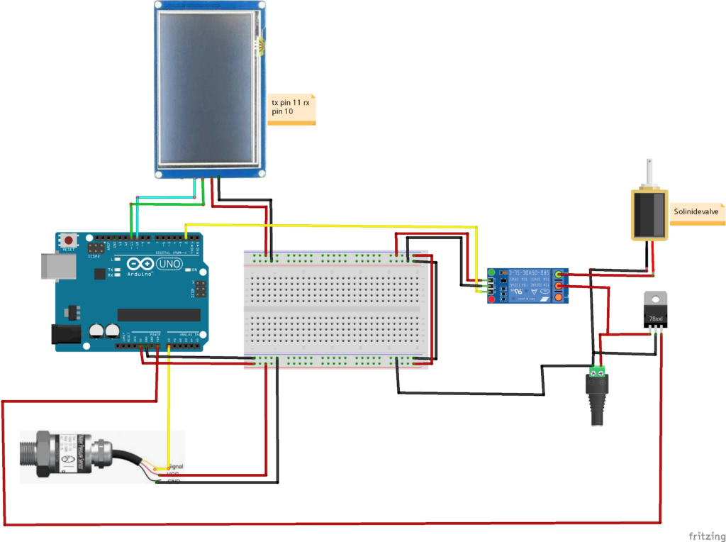
❖Pressure Sensor Interface
- The Bosch pressure sensor outputs an analog voltage
- Connected to an Arduino analog pin
- Voltage varies proportionally with applied pressure
The Arduino converts this voltage into:
- Pressure in MPa
- Pressure in PSI (used internally for logic)
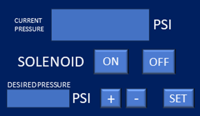
❖Nextion Display Communication
- Connected using SoftwareSerial
- TX and RX pins allow two-way communication
- Used to:
- Display current pressure
- Accept user-defined pressure setpoints
- Show system status (LOW / NORMAL)
Recommended Reading:
Irrigation Scheduling and Water Pumps Control using Touch LCD and Arduino Uno
❖Relay & Solenoid Control
- Relay module driven by Arduino digital pin
- Relay switches 12V DC solenoid valve
- Solenoid controls fluid flow to regulate pressure
❖Power Management
- A 12V to 5V DC converter safely powers Arduino and relay
- Prevents voltage instability in industrial environments
Arduino Code for Pressure Monitoring & Control Using Nextion HMI
include <SoftwareSerial.h>
SoftwareSerial mySerial(10, 11); // Define a SoftwareSerial object named mySerial with RX pin 10 and TX pin 11

#define Relay 2 // Define the pin number for the relay

int Desired_P;
float Current_P, Current_P_Mpa, Set_P; // Declare variables to store desired pressure, current pressure, and set pressure
float Tolerance = 20; // Define the tolerance for pressure readings
unsigned long pms; // Declare a variable to store the time for updating the screen
float P_n = 1; // Nominal Pressure
float C_o = 0.1;
float C_1 = 0.8;
float V_s = 5;
bool Set=false, LOW_P=false;;
 int  Current_PP;


int CF = -400;

void setup()
{
  // Open serial communications with the default baud rate and wait for the port to open
  Serial.begin(9600);
  mySerial.begin(9600);

  // Set the relay pin as an output
  pinMode(Relay, OUTPUT);
  // Turn off relay
  digitalWrite(Relay, HIGH); // Turn Off relay initially
  // Wait for 1 second
  delay(1000);
}
Code Functionality Explanation
→Libraries Used
- SoftwareSerial – For Nextion communication
→Setup Function Logic
During initialization, the system:
- Starts serial communication
- Initializes Nextion display
- Configures relay pin as output
- Sets default system states
- Prepares pressure calculation constants
→Main Loop Operation
The loop continuously executes the following steps:
→Pressure Sensor Data Acquisition
- Reads analog sensor value multiple times
- Averages readings to reduce noise
- Converts ADC value into output voltage
→Pressure Calculation Logic
The code applies calibration constants:
- Converts voltage into MPa
- Converts MPa into PSI
- Filters invalid voltage ranges
- Ensures accurate industrial-grade readings
This reflects professional sensor calibration practices used in product development.
→Desired Pressure Input (HMI)
- User enters desired pressure via Nextion display
- Arduino stores this as Set Pressure
- Tolerance range is applied for safe operation
→Smart Decision Logic (Pressure Control)
The Arduino compares:
- Current Pressure
- Desired Pressure
- Tolerance Value
If pressure is below the setpoint:
- Relay turns ON
- Solenoid opens
- Pressure increases
If pressure exceeds limit:
- Relay turns OFF
- Solenoid closes
- Pressure stabilizes
This logic makes the system a true Smart Pressure Regulation System.
→Nextion Display Updates
- Pressure values updated at timed intervals
- System status sent to HMI
- Reduces serial load and flickering
Please Also Check:
Powder Dispenser Machine with Nextion Touch LCD and Arduino
Key Features of Industrial Pressure Automation System
- Industrial-grade pressure monitoring
- Touchscreen HMI control
- Automatic solenoid regulation
- Safe tolerance-based logic
- Expandable for IoT & PLC systems
Applications of System
- Industrial fluid systems
- Hydraulic pressure regulation
- Laboratory pressure control
- Agricultural irrigation systems
- Custom industrial product design
Future Enhancements
- PID-based pressure control
- Data logging via SD card
- ESP32-based IoT monitoring
- Cloud dashboard integration
- Multi-sensor pressure zones
Conclusion
The Pressure Regulator with Arduino and Nextion Display is a powerful example of how embedded systems can be transformed into smart industrial products. By combining accurate sensing, intelligent control logic, and user-friendly HMI, this project meets real-world automation requirements.
At Arduino Expert, we specialize in delivering reliable, scalable, and production-ready smart systems.
Need Assistance in Smart Pressure Control System Project?
If you need this Pressure Control System Project with or without Modifications or Customization then you can contact us through WhatsApp. We can deliver you this Project in the Following Ways.
Project Code:
we can provide you Project Code along with Zoom Assistant, through Zoom meeting for Setup of this Project.
Fully Functional Project with Hardware/Components Shipment:
if you can not make this project yourself then you can use this option. We will assemble the Project and will ship it to your Doorstep with Safe Packaging.
Learn More about the services we offer.